
Implantable medical electrical stimulation lead, such as pne lead, and method of use

a technology of medical electrical stimulation and implantable leads, which is applied in the direction of internal electrodes, spinal electrodes, therapy, etc., can solve the problems of poor stimulation, low success rate of surgical procedures, and high likelihood of electrode dislocation, so as to promote minimally invasive insertion and inhibit the axial migration of the lead body. , the effect of high pliableness

Inactive Publication Date: 2010-10-21
MEDTRONIC INC
View PDF15 Cites 29 Cited by
  • Summary
  • Abstract
  • Description
  • Claims
  • Application Information

AI Technical Summary

Benefits of technology

The lead effectively resists migration and dislodgement, providing stable electrical stimulation with reduced patient discomfort and improved treatment efficacy during temporary sacral nerve stimulation procedures.

Problems solved by technology

Many pharmaceuticals do not adequately resolve the issue and can cause unwanted side effects; further, a number of surgical procedures have a low success rate and / or are not reversible.
For example, any pulling or tugging on the proximal end of the lead body (from outside of the patient's body) could be directly communicated to the lead's electrode, thus creating a higher likelihood of electrode dislodgement and poor stimulation.
The ground pad may cause the patient some discomfort, and in some instances can become dislodged or disconnected during the test period, thus preventing the test stimulation therapy from occurring.

Method used


Image

  • Implantable medical electrical stimulation lead, such as pne lead, and method of use
  • Implantable medical electrical stimulation lead, such as pne lead, and method of use
  • Implantable medical electrical stimulation lead, such as pne lead, and method of use

Examples


Embodiment Construction

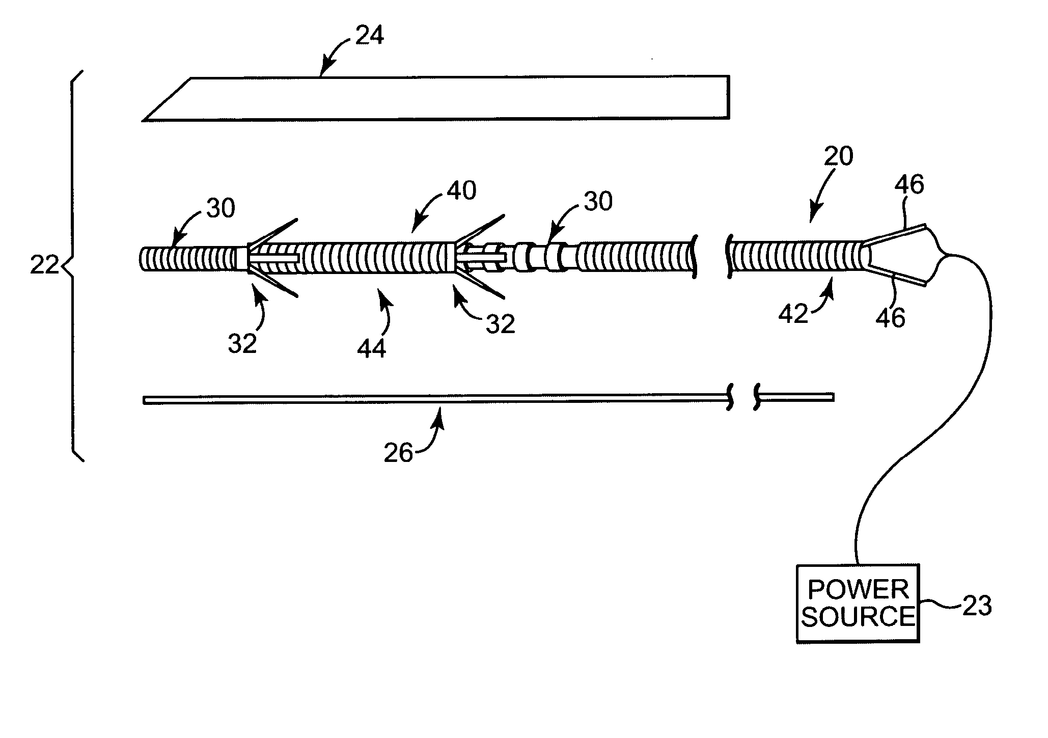
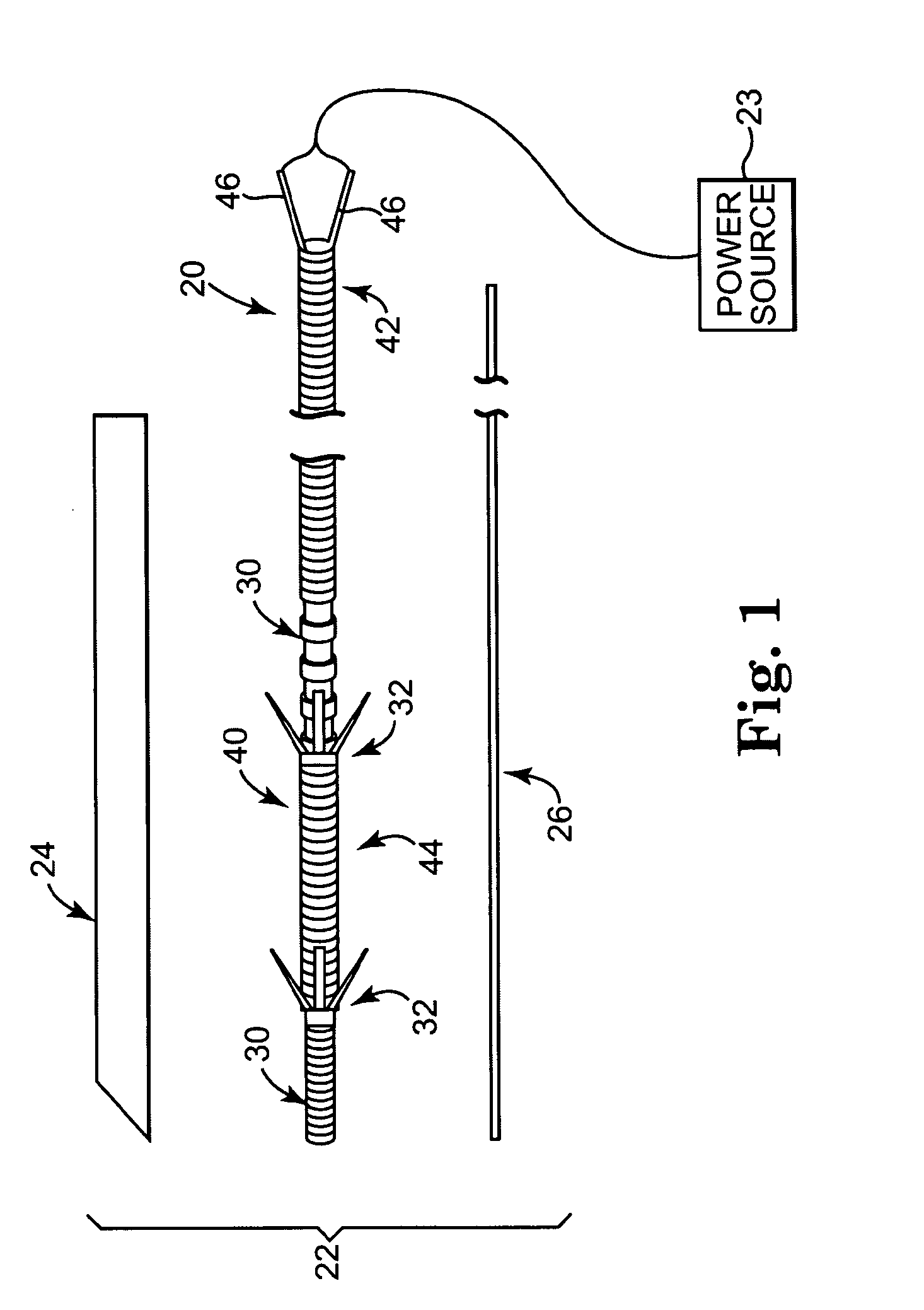
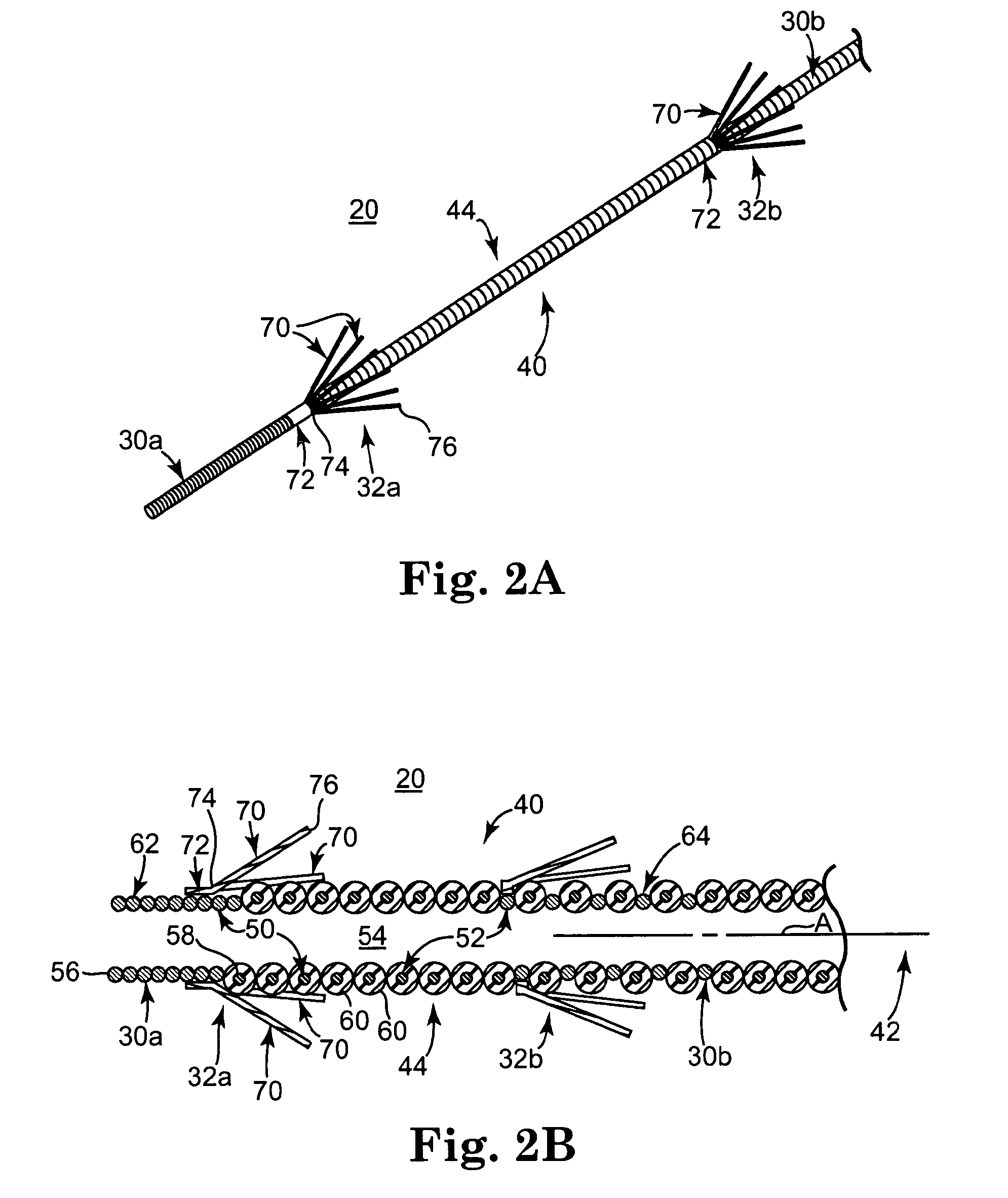
[0024]One embodiment of a medical electrical lead 20 in accordance with principles of the present invention is shown in simplified form in FIG. 1 as part of a system 22 useful for delivering stimulation energy to a patient (not shown) via a power source 23 (that may or may not be considered part of the system 22). The system 22 can assume a variety of forms, and can include components apart from those shown in FIG. 1. In one embodiment, however, the system 22 includes the lead 20, as well as a needle 24 and a stylet 26. Details on the various components are provided below. In general terms, however, the lead 20 forms at least one exposed electrode surface 30, and is sized to be slidably received within the needle 24. The stylet 26 is sized to be slidably received within the lead 20. Finally, the power source 23 is electrically coupled to the lead 20 for providing electrical stimulation to the exposed electrode surface(s) 30. As described in greater detail below, the lead 20 is of a ...


PUM


Abstract

An implantable medical electrode lead for stimulation of bodily tissue. The lead is adapted for use with a needle lumen diameter of not greater than 0.05 inch, and includes a lead body and a tine assembly. The lead body has a distal section forming at least one exposed electrode surface. The tine assembly includes a plurality of tines each having a base end coupled to an exterior of the lead body immediately adjacent the exposed electrode surface and a free end that is movable relative to the lead body to inhibit axial migration of the lead body upon implantation into a patient. In one embodiment, the lead body is a PNE lead and provides two electrode surfaces for bipolar operation.

Description

BACKGROUND OF THE INVENTION[0001]The present invention relates to systems and methods for providing electrical stimulation to bodily tissue, such as a portion of a patient's nervous system. More particularly, it relates to temporarily implantable electrical leads, such as a peripheral nerve evaluation lead used to stimulate a sacral nerve, that resist migration and, in some embodiments, are bipolar.[0002]A number of human bodily functions are affected by the nervous system. For example, bodily disorders, such as urinary incontinence, urinary urge / frequency, urinary retention, pelvic pain, bowel dysfunction (constipation, diarrhea, etc.), erectile dysfunction, etc., are all bodily functions influenced by the sacral nerves. As a point of reference, urinary incontinence is the involuntary loss of control over the bladder. Incontinence is primarily treated through pharmaceuticals and surgery. Many pharmaceuticals do not adequately resolve the issue and can cause unwanted side effects; f...

Claims


Application Information

Patent Timeline
Patent Type & Authority Applications(United States)
IPC IPC(8): A61N1/05
CPCA61N1/0558
Inventor BONDE, ERIC H.STETZ, ERIC M.TRONNES, CAROLE A.
Owner MEDTRONIC INC
Learn More