
Temperature control device

Active Publication Date: 2010-10-07
METTLER TOLEDO GMBH
View PDF5 Cites 16 Cited by
  • Summary
  • Abstract
  • Description
  • Claims
  • Application Information

AI Technical Summary

Benefits of technology

[0011]The separation of reactor cooling device and reactor heating device is very advantageous because the individual components can be operated in an optimal way and a significantly broader temperature range can be covered. The temperature range of a calorimeter that is covered by a temperature control unit depends primarily on the maximum cooling power that can be generated by the thermoelectric reactor-cooling device and the maximum heating power that can be generated by the reactor-heating device.
[0044]Arrangements where a temperature control device according to the invention is used in combination with a calorimeter are very desirable because, in comparison to calorimeters of the known state of the art, the size of the instrument as a whole can be reduced and the temperature control device can be operated with a more efficient use of energy, whereby a more cost-effective production of the device is made possible.

Problems solved by technology

The reaction calorimeters described above have the disadvantage that they cover only a relatively small temperature range from about −30° C. to about +150° C. and, further, that a large, voluminous and powerful electric supply is required, with the result that the control of the internal reactor temperature becomes cumbersome and slow.
These requirements, which besides fast and efficient temperature control over a wide temperature range also include the size and compact design of the thermostat as well as cost-effectiveness and efficient use of resources, are difficult to realize particularly for larger sample volumes.

Method used


Image

  • Temperature control device
  • Temperature control device
  • Temperature control device

Examples


Embodiment Construction

)

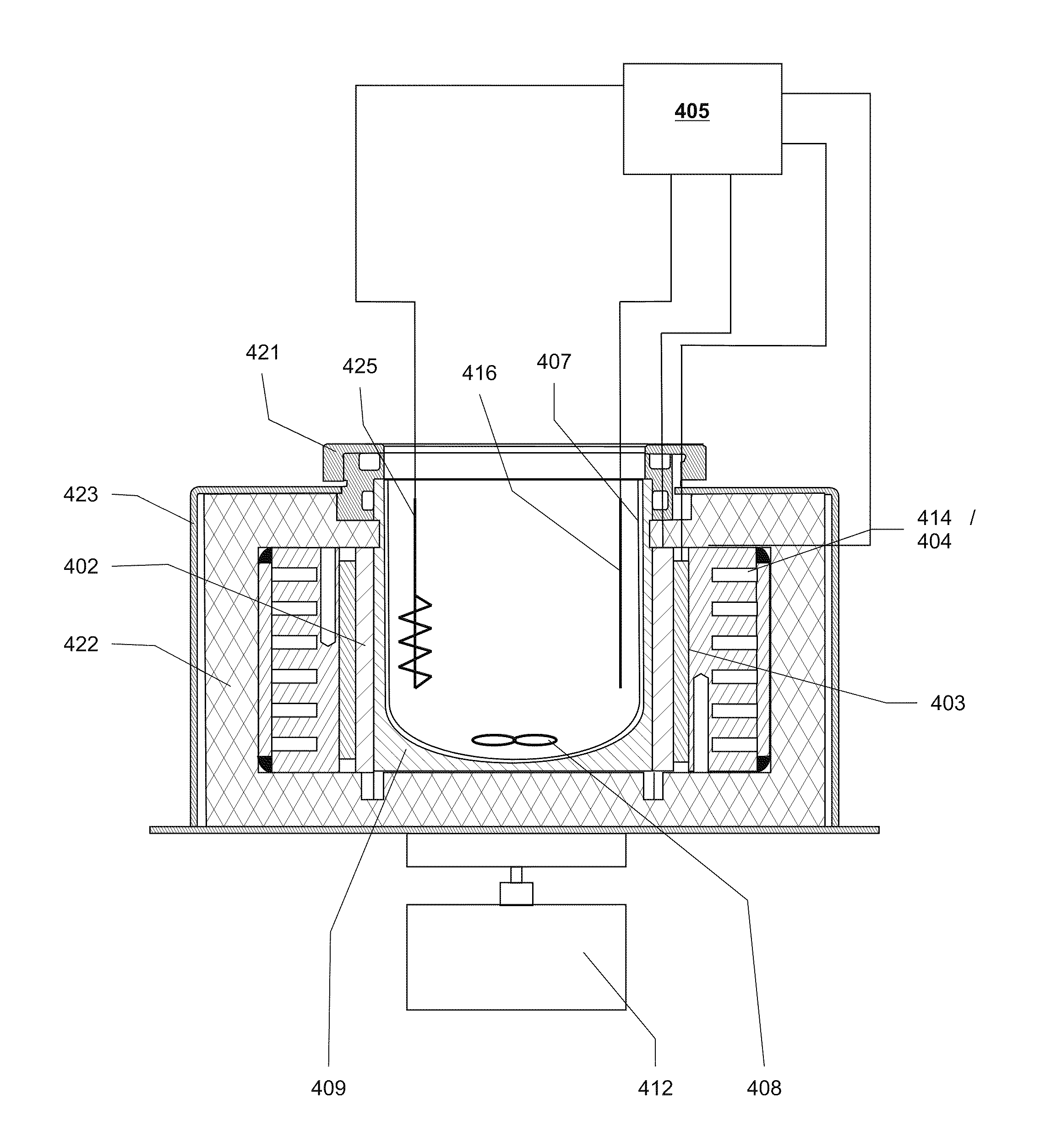
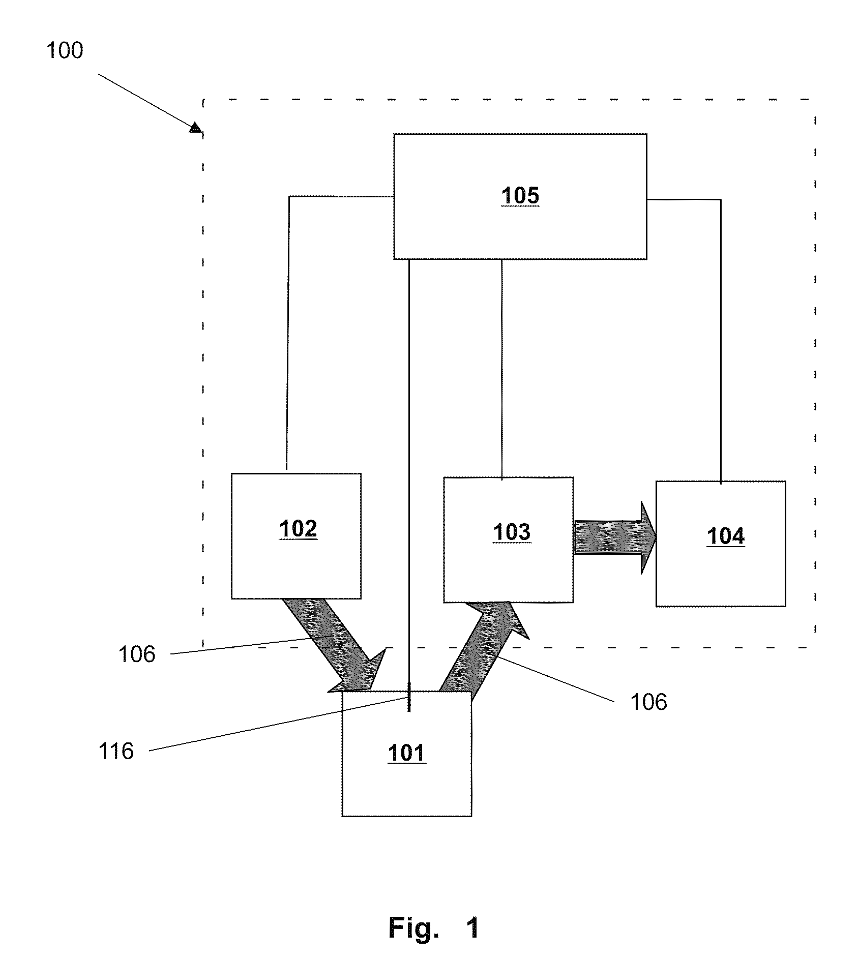
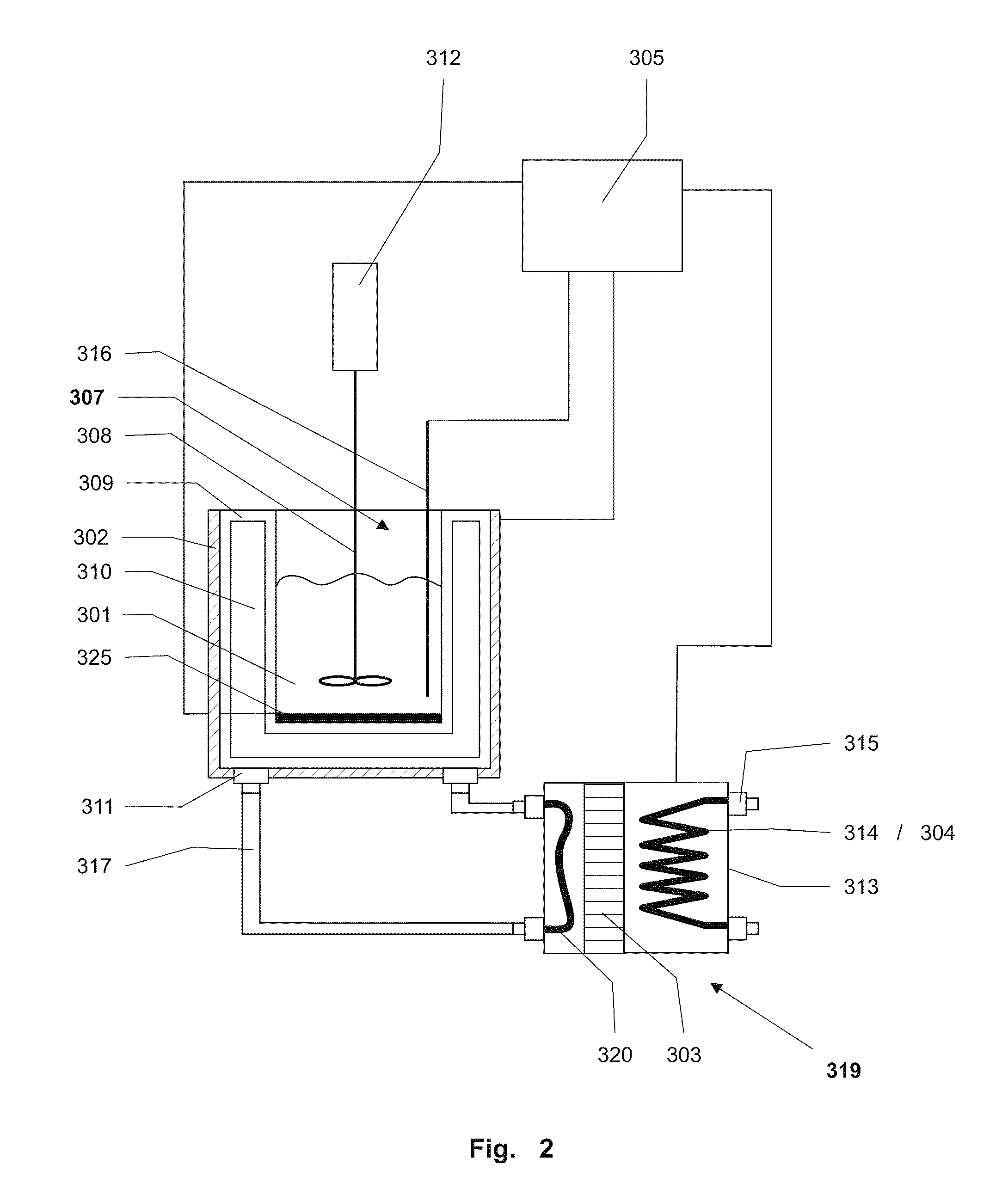
[0050]FIG. 1 shows, in a greatly simplified schematic view, the basic structure and functional concept of an exemplary temperature control device 100 of the present invention. As shown, a sample 101 may be arranged in a reactor and thermally connected to the temperature control device 100, which contains a reactor-heating device 102, a reactor-cooling device with a thermoelectric cooling element 103, and a coolant 104 that is thermally connected to the thermoelectric cooling element 103. The regulation and / or control of the temperature control device 100 takes place by way of a control and / or regulation unit 105 which also supplies the electric current required for the operation of the individual elements. The control and / or regulation unit 105 is further connected to at least one temperature sensor 116 that serves to measure the sample temperature, i.e., the actual temperature inside the reactor.

[0051]The heat flow between the thermostat 100 and sample 101 is symbolized here by ar...


PUM


Abstract

A calorimeter with at least one reactor for receiving a sample. A reactor jacket may surround the reactor. A reactor-heating device and a reactor-cooling device serve to regulate an internal reactor temperature. The reactor-cooling device preferably comprises a thermoelectric cooling element that is thermally connected to a coolant. The reactor-cooling device and the reactor-heating device are preferably individual units, both of which are thermally connected to the reactor by way of the reactor jacket. A temperature control device is provided to control the reactor-heating device and the reactor-cooling device.

Description

CROSS-REFERENCE TO RELATED APPLICATIONS[0001]This application is a continuation under 35 USC §120 of PCT / EP2008 / 063364, filed 7 Oct. 2008 which is, in turn, entitled to benefit of a right of priority under 35 USC §119 from European patent application 07119294.2, filed 25 Oct. 2007. The content of each of these applications is incorporated by reference as if fully recited herein.TECHNICAL FIELD[0002]The present invention is directed to a calorimeter, such as a reaction calorimeter. More specifically, the present invention is directed to a calorimeter, a temperature control device for use with an apparatus having a calorimeter, and a method of use thereof.BACKGROUND[0003]Reaction calorimeters are used, among other purposes, for the determination of chemical and / or physical parameters of a sample. The use of a fast and efficient temperature control device is important in particular for the investigation of temperature-critical samples. In temperature-critical samples it is possible tha...

Claims


Application Information

Patent Timeline
IPC IPC(8): G01N25/20G01N35/00
CPCG01K17/04G01N25/4826Y10T436/115831Y10T436/11G01N25/4833
Inventor SCHENKER, BENEDIKT
Owner METTLER TOLEDO GMBH
Learn More