Eureka AIR delivers breakthrough ideas for toughest innovation challenges, trusted by R&D personnel around the world.

Secondary surveillance radar and method of analyzing replies for secondary surveillance radar

a secondary surveillance radar and surveillance radar technology, applied in the direction of navigation instruments, using reradiation, instruments, etc., can solve the problem of possible inability to correct collision alerts, and achieve the effect of improving the ability to eliminate unnecessary alerts

Active Publication Date: 2010-10-07
KK TOSHIBA
View PDF18 Cites 8 Cited by
  • Summary
  • Abstract
  • Description
  • Claims
  • Application Information

AI Technical Summary

Benefits of technology

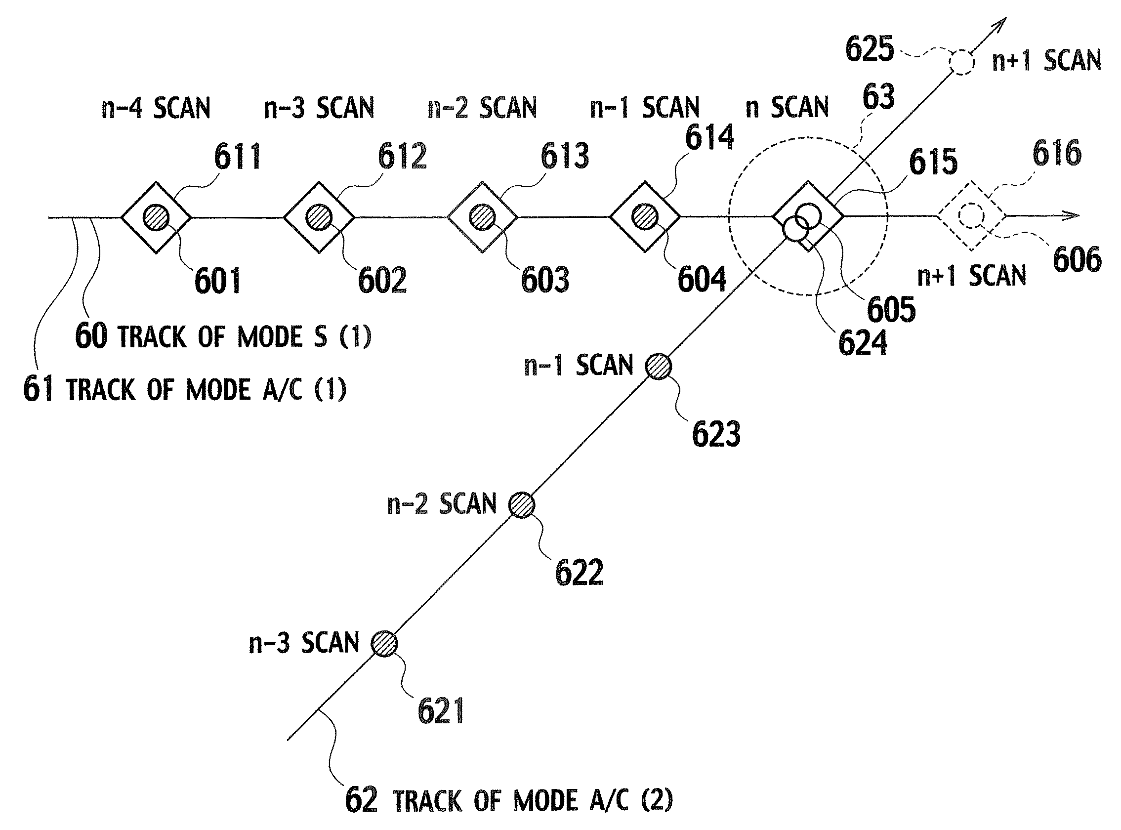
[0018]The present invention has been made in consideration of the abovementioned problems in the conventional technology. An object of the present invention is to provide a secondary surveillance radar and a method of analyzing replies for secondary surveillance radar, which are improved in capability of eliminating an unnecessary Mode A / C target report.
[0021]According to the present invention, it becomes possible to correctly make judgment on whether or not the Mode A / C target report can be rejected, and to provide the secondary surveillance radar and the method of analyzing replies for secondary surveillance radar, which are improved in capability of eliminating an unnecessary Mode A / C target report.

Problems solved by technology

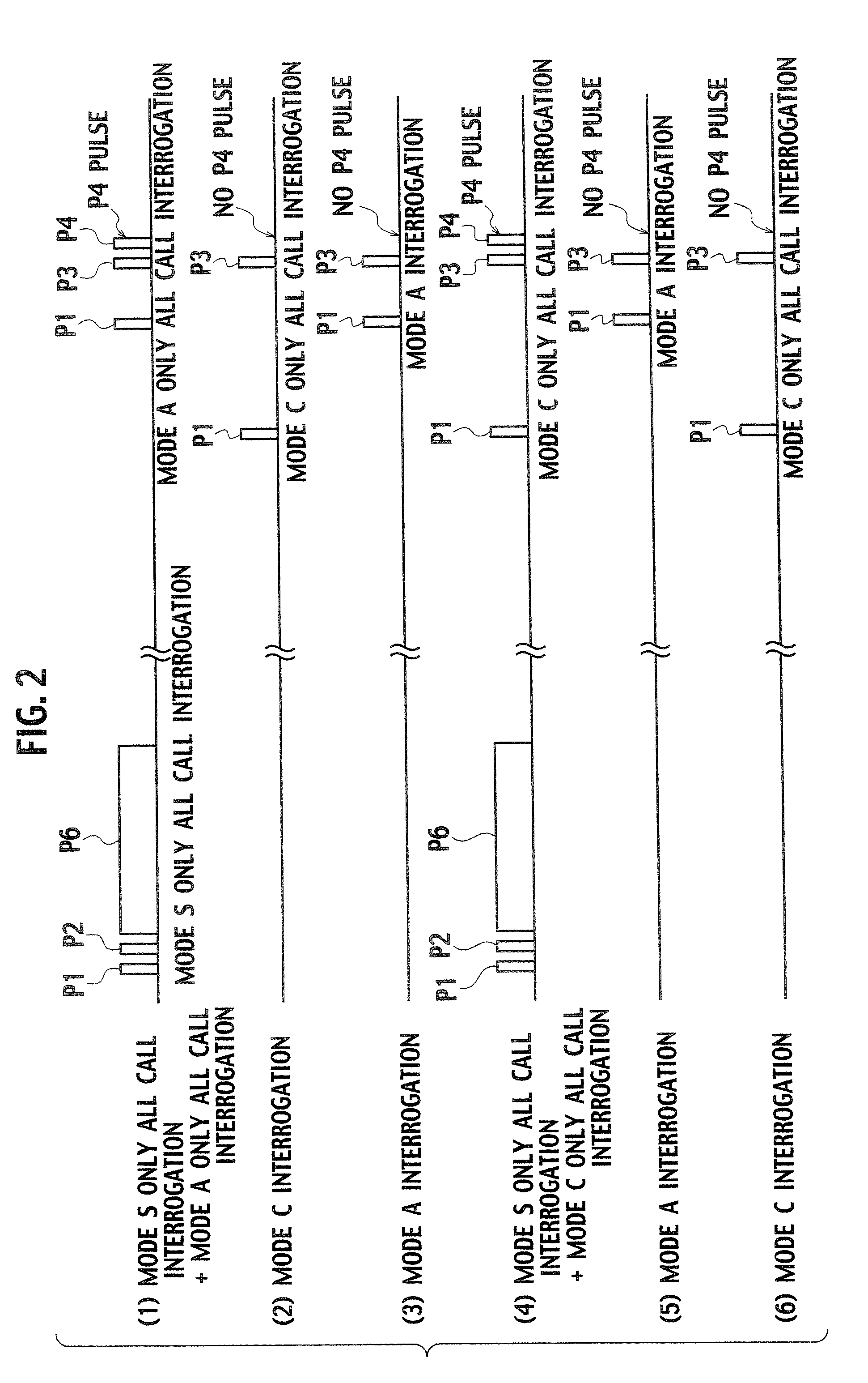
However, even in this case, this interrogator receives not only a Mode S reply but also an unnecessary Mode A / C reply from the same aircraft.
However, in the abovementioned combiner, there are problems as described below.
However, in a case where a Mode A validity (Va) and a Mode C validity (Vc) in the Mode A / C target report are low (zero), this Mode A / C target report may possibly have been transmitted from another aircraft, and thus cannot be rejected (eliminated).
Additionally, an incorrect collision alert may possibly be issued on the basis of the Mode A / C target report that has not been rejected.

Method used


Image

  • Secondary surveillance radar and method of analyzing replies for secondary surveillance radar
  • Secondary surveillance radar and method of analyzing replies for secondary surveillance radar
  • Secondary surveillance radar and method of analyzing replies for secondary surveillance radar

Examples


Embodiment Construction

[0027]An embodiment of the present invention will be described below on the basis of the drawings. Note that the following embodiment is provided merely for the purpose of explaining the present invention, and is not intended to limit the scope of the present invention. Accordingly, while any person skilled in the art can adopt various embodiments each including any one of, or all of elements of the embodiment, such embodiments are also included in the scope of the present invention. Additionally, in all of the drawings for explaining the following embodiment, the same reference numerals are given to the corresponding elements, and repetitive explanations thereon will be omitted.

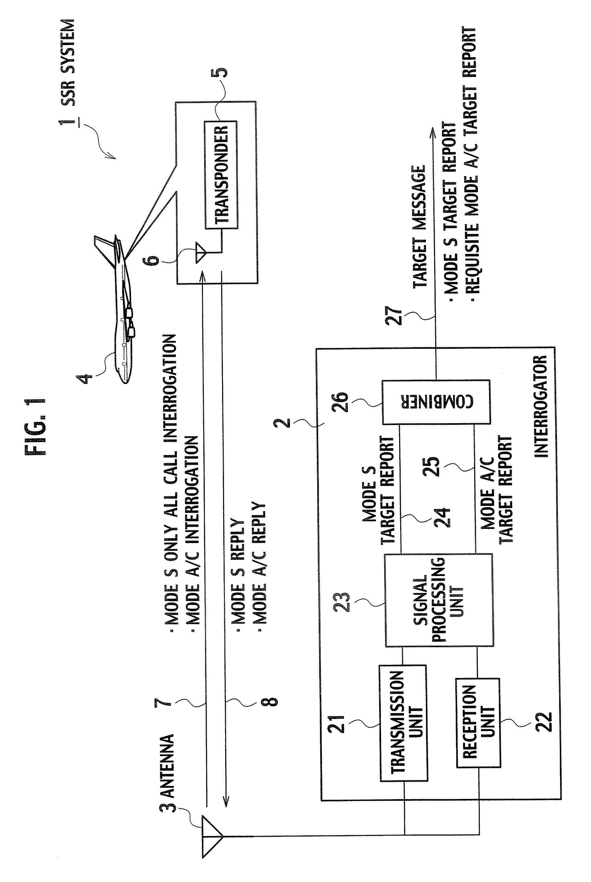
[0028]FIG. 1 is a block diagram of an SSR (Secondary Surveillance Radar) system 1 according to one embodiment of the present invention. This SSR system 1 includes an interrogator 2, an antenna 3, a transponder 5 and an antenna 6. The interrogator 2 and the antenna 3 are placed on the ground, and the antenna ...


PUM


Abstract

Provided is a secondary surveillance radar with an improved capability of eliminating an unnecessary Mode A / C target report, which includes a transmission unit transmitting interrogations, a reception unit receiving replies, from a transponder, corresponding respectively to the interrogations, and a signal processing unit generating a Mode S target report and a Mode A / C target report from the replies. The radar also includes a combiner generating a Mode S track and a Mode A / C track respectively from the Mode S and the Mode A / C reports, and then judging whether the Mode S report and the Mode A / C report are of the same target on the basis of the Mode S and the Mode A / C tracks. When the Mode S and the Mode A / C reports are of the same target, the combiner rejects the Mode A / C report.

Description

BACKGROUND OF THE INVENTION[0001]1. Field of the Invention[0002]The present invention relates to a secondary surveillance radar and a method of analyzing replies for secondary surveillance radar, which receives replies corresponding respectively to interrogations transmitted to a transponder of an aircraft, and which analyzes contents of the replies.[0003]2. Description of the Related Art[0004]Radars for aircraft surveillance which are used for air traffic control are broadly divided into a primary surveillance radar (PSR) and a secondary surveillance radar (SSR).[0005]The PSR is designed to acquire information on a position of an aircraft by sending out radio waves from the ground, and by receiving and processing reflection waves thereof.[0006]On the other hand, the SSR is designed to obtain various kinds of information on an aircraft as follows. In the SSR, interrogations are transmitted from an interrogator placed on the ground equipment to a transponder installed in an aircraft....

Claims


Application Information

Patent Timeline
IPC IPC(8): G01S13/91G01S13/93G01S13/87
CPCG01S13/782
Inventor INO, MASAMI
Owner KK TOSHIBA
Why Eureka
Eureka Blog
Learn More