
Positioning system for tissue removal device

a tissue removal and positioning system technology, applied in the field of tissue cutting devices, can solve the problems of severe health risks to patients afflicted, deterioration of motor skills, headaches, behavioral changes, etc., and achieve the effect of ensuring the safety of patients

Active Publication Date: 2010-09-30
NICO CORP
View PDF68 Cites 40 Cited by
  • Summary
  • Abstract
  • Description
  • Claims
  • Application Information

AI Technical Summary

Problems solved by technology

Various abnormalities of the neurological system, such as brain and spinal tumors, cysts, lesions, or neural hematomas, can cause severe health risks to patients afflicted by them, including deterioration in motor skills, nausea or vomiting, memory or communication problems, behavioral changes, headaches, or seizures.
However, given the complexity and importance of the neurological system, such neurosurgical procedures are extremely delicate and must be executed with great precision and care.
Many known tissue cutting devices suffer from an inability to quickly and cleanly sever neurological tissue samples without causing “traction” or pull on the surrounding tissue.
In addition, many known devices are not configured to both “debulk” large structures and to finely shave smaller, more delicate structures and lack the flexibility needed in many procedures.
Furthermore, many neurological procedures impose significant space limitations on the surgeon, and the tissue resection device needs to be manipulable by the surgeon with one hand in relatively small spaces.
Many known devices either emulsify the resected tissue, macerate the resected tissue, or thermally damage the tissue rendering it unsuitable for subsequent analysis (e.g., pathologic and / or histologic analysis) which is necessary for the determination of the most effective post resection treatment therapies.

Method used


Image

  • Positioning system for tissue removal device
  • Positioning system for tissue removal device
  • Positioning system for tissue removal device

Examples


Embodiment Construction

[0045]Referring now to the discussion that follows, and also to the drawings, illustrative approaches to the disclosed systems and methods are shown in detail. Although the drawings represent some possible approaches, the drawings are not necessarily to scale and certain features may be exaggerated, removed, or partially sectioned to better illustrate and explain the present disclosure. Further, the descriptions set forth herein are not intended to be exhaustive, or otherwise limit or restrict, the claims to the precise forms and configurations shown in the drawings and disclosed in the following detailed description.

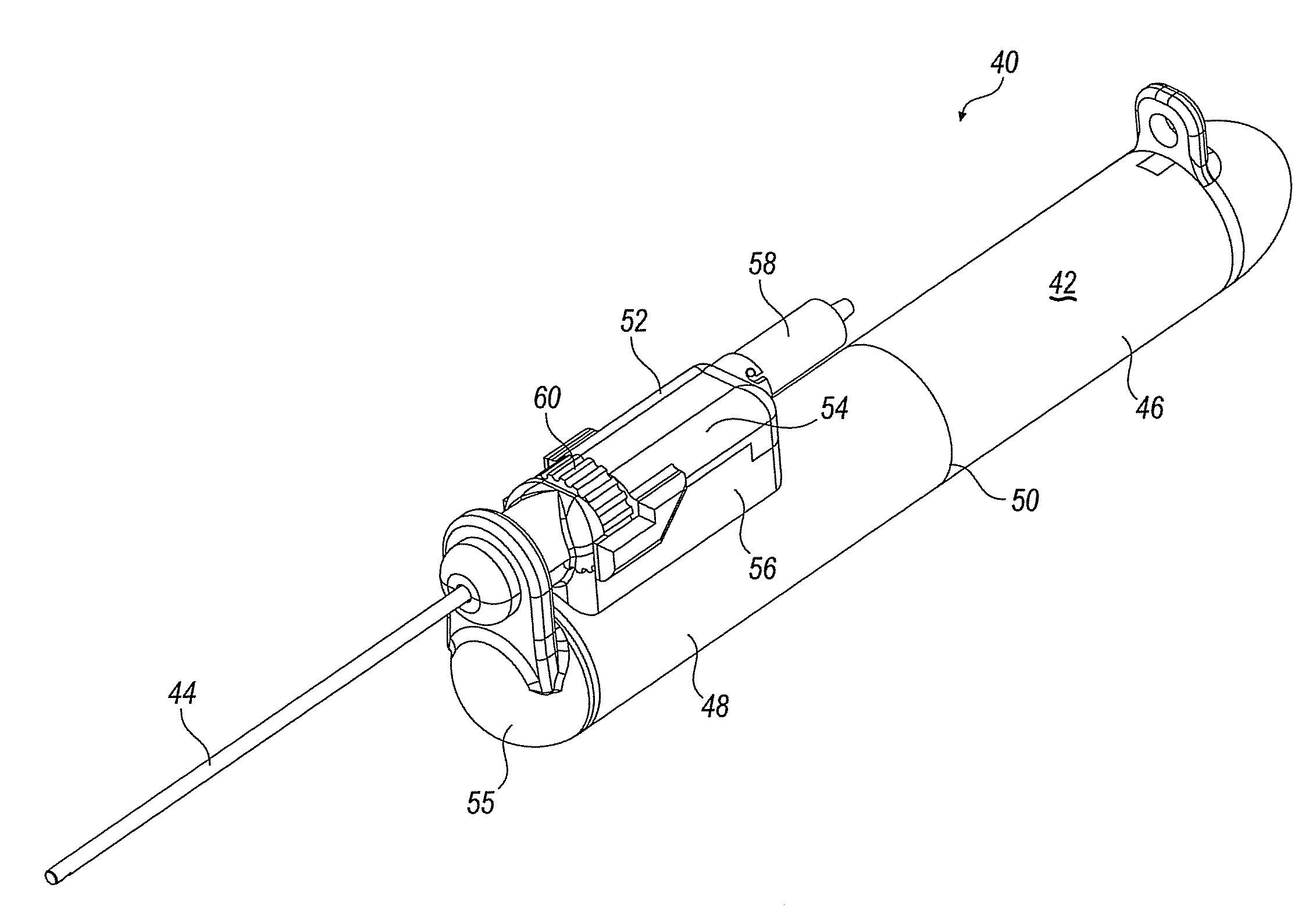
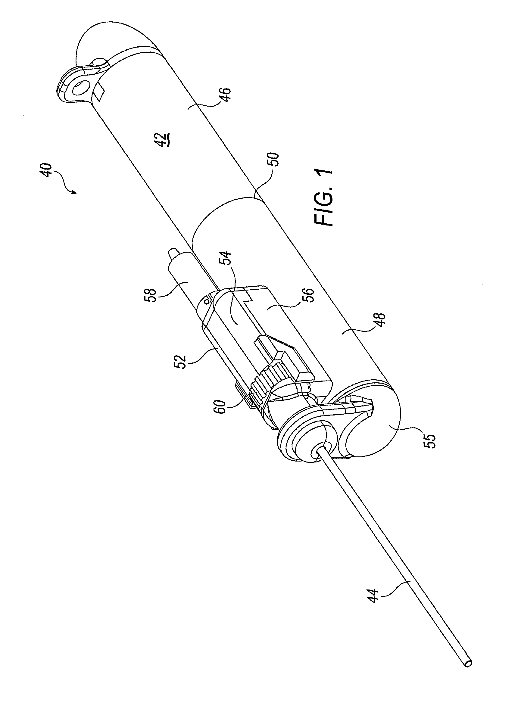
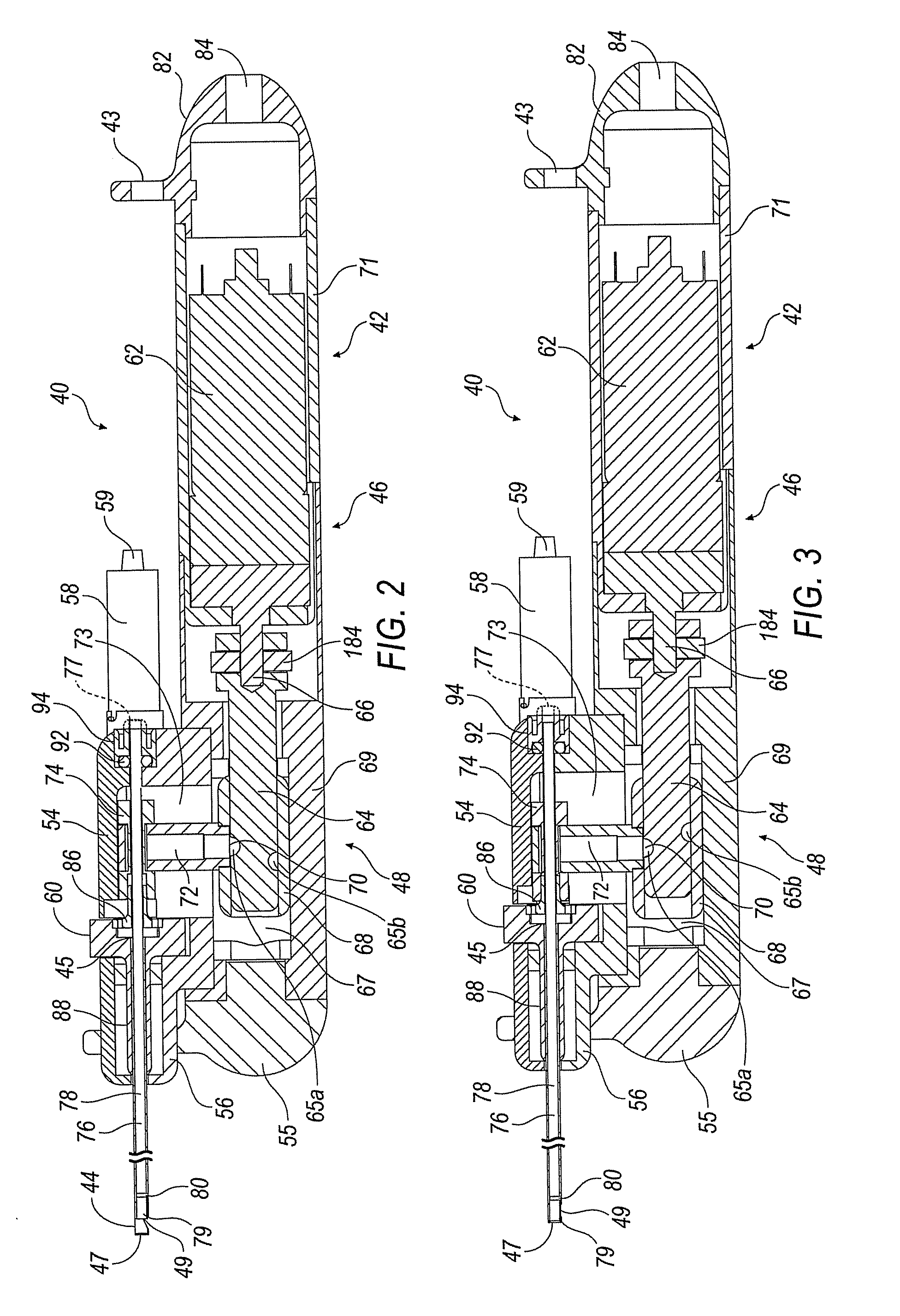
[0046]Described herein are tissue cutting devices that are suited for neurosurgical applications such as the removal of spine and brain tissue. The devices are configured to provide high speed reciprocation, variable aspiration, and / or combinations of both high speed reciprocation and variable aspiration. As a result, the tissue cutting devices of the present disclosure...


PUM


Abstract

A tissue cutting device especially suited for neurosurgical applications is disclosed and described. The device includes a handpiece and an outer cannula in which a reciprocating inner cannula is disposed. At least one position transducer for tracking a location in space of the tissue cutting device is rigidly associated with the handpiece. The position transducer is operable for sending a signal indicative of a location of a distal end of the outer cannula. The tissue cutting device may also include an angular position sensor for determining an angular position of the outer cannula relative to the position transducer.

Description

CROSS-REFERENCE TO RELATED APPLICATIONS[0001]This application is a continuation-in-part of U.S. application Ser. No. 12 / 481,219, filed on Jun. 9, 2009, which is a continuation-in-part of U.S. Application No. 12,475,258, filed on May, 29, 2009, which is a continuation-in-part of U.S. application Ser. No. 12 / 435,724, filed on May 5, 2009, which is a continuation-in-part of U.S. application Ser. No. 12 / 404,407, filed on Mar. 16, 2009, which is a continuation-in-part of U.S. application Ser. No. 12 / 391,579, filed on Feb. 24, 2009, which is a continuation-in-part of U.S. application Ser. No. 12 / 389,447, filed on Feb. 20, 2009, which is a continuation-in-part of U.S. application Ser. No. 12 / 336,054, filed Dec. 16, 2008 and U.S. application Ser. No. 12 / 336,086, filed Dec. 16, 2008, each of which is hereby incorporated by reference in its entirety.TECHNICAL FIELD[0002]The present disclosure relates to tissue cutting devices, in particular, tissue cutting devices that are suited for neurosur...

Claims


Application Information

Patent Timeline
IPC IPC(8): A61B17/32
CPCA61B1/313A61B10/0275A61B10/0283A61B17/32002A61B2010/0208A61B2017/00398A61B2017/306A61B2017/320028A61B2017/3445A61B2217/005A61B2090/3983A61B2034/2055A61B34/20A61B34/70A61B90/50A61B90/11A61B2034/2051
Inventor MARK, JOSEPH L.
Owner NICO CORP
Learn More