Optical sheet and method for producing the same
- Summary
- Abstract
- Description
- Claims
- Application Information
AI Technical Summary
Benefits of technology
Problems solved by technology
Method used
Image

Examples
first embodiment
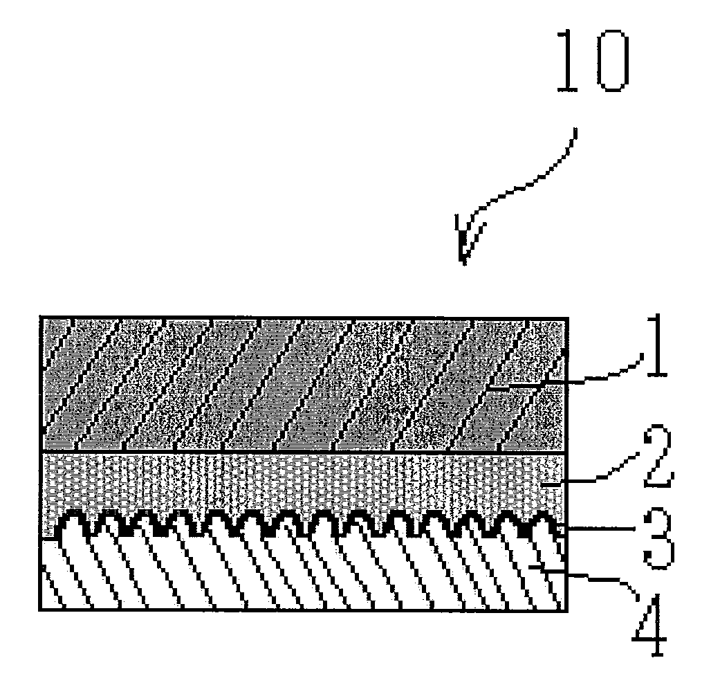
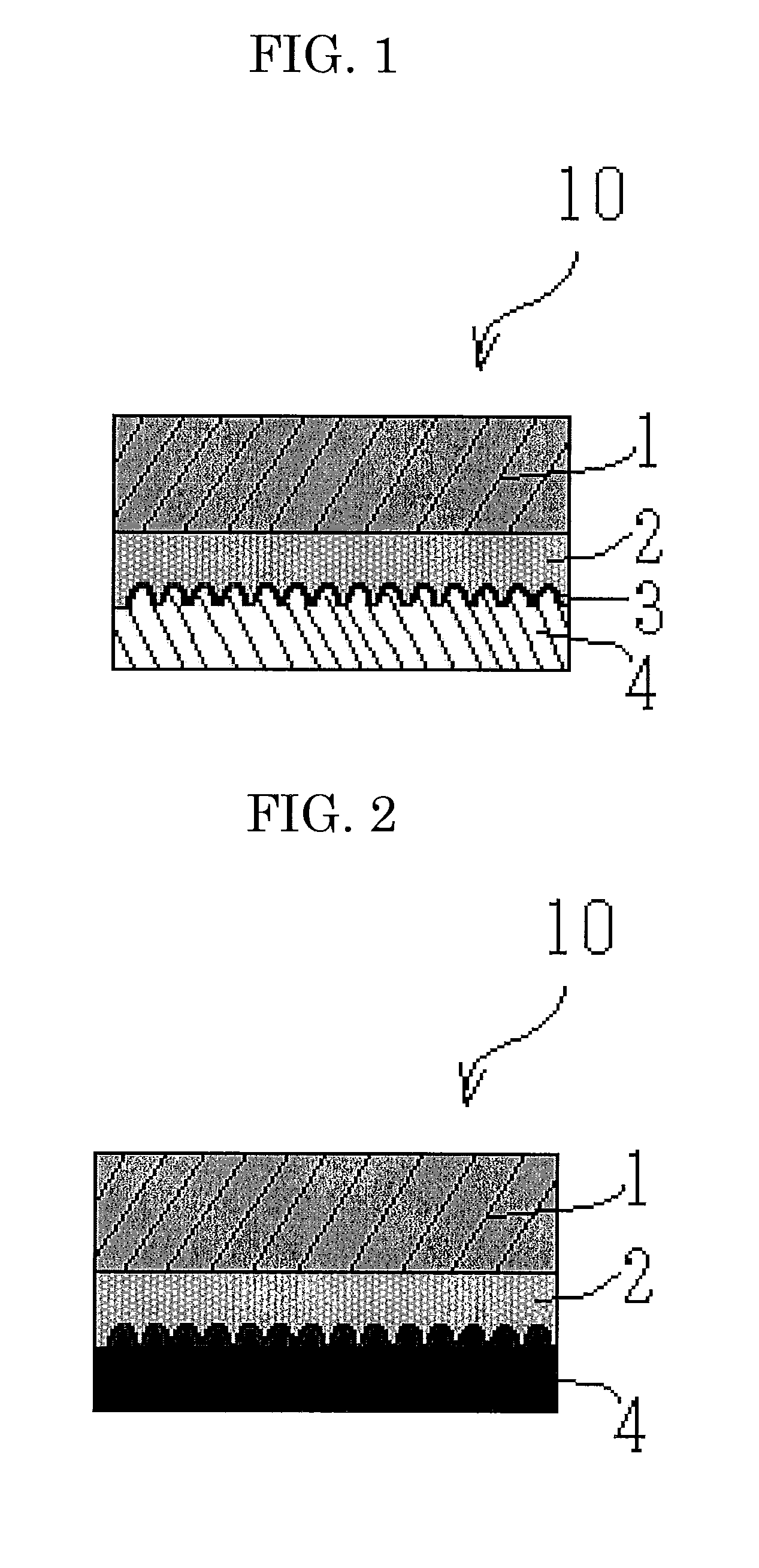
[0088]In a first embodiment, the method of the present invention for producing an optical sheet includes at least a coating step, a second layer-forming step and a first layer-forming step; and, if necessary, further includes a laminate forming step and other steps.
>
[0089]The coating step is a step of coating a support film with a curable resin as a light-transmissive material.
[0090]The support film and the curable resin are previously described.
[0091]The thickness of the curable resin coated is not particularly limited and may be appropriately determined depending on the purpose. It is preferably 3 μm to 30 μm.
[0092]The method for coating the curable resin is not particularly limited and may be appropriately selected depending on the purpose. Examples thereof include extrusion coating, bar coating, gravure coating and roll coating.
>
[0093]The second layer-forming step is a step of forming a second layer by curing the curable resin while a mold having a concavo-convex pattern in a su...
second embodiment
[0131]In a second embodiment, a method of the present invention for producing an optical sheet includes at least a first layer-forming step and a second layer-forming step; and, if necessary, further includes an attaching step and other steps.
>
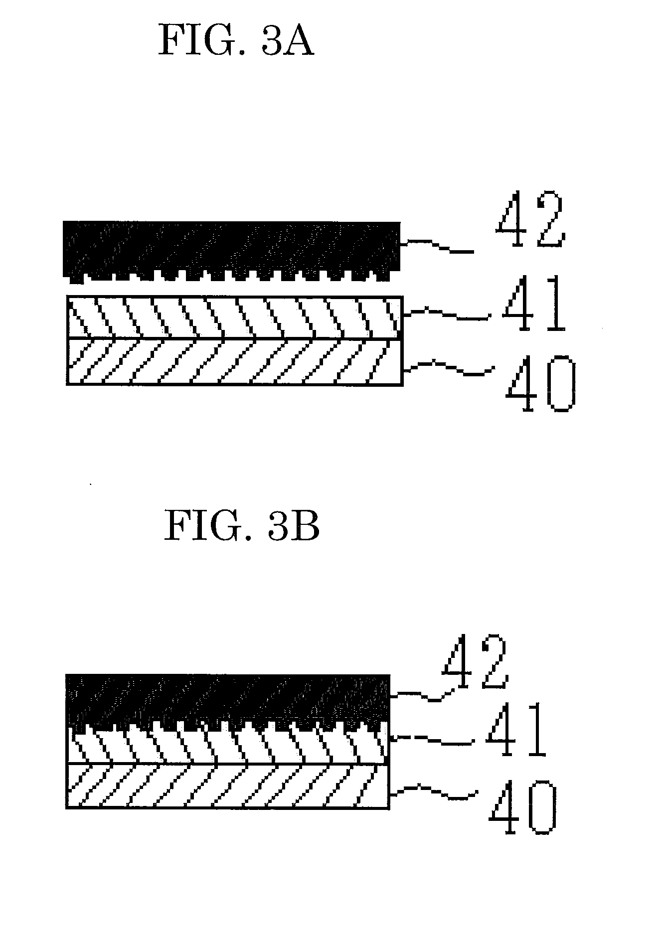
[0132]The first layer-forming step is a step of forming a first layer by forming a concavo-convex pattern in a light-reflective sheet superposed on and thermally pressure-bonded to a surface of a mold. By pressure-bonding the light-reflective sheet to the surface of the mold, the concavo-convex pattern of the mold is transferred to the light-reflective sheet. Thereafter, the mold is separated from the light-reflective sheet.
[0133]The mold is previously described.
[0134]The light-reflective sheet is not particularly limited, so long as at least a surface thereof is made of a reflective material, and may be appropriately selected depending on the purpose. Examples thereof include sheets in which a film of a reflective material (e.g., silver and a...
third embodiment
[0153]In a third embodiment, the method of the present invention for producing an optical sheet includes at least a concavo-convex pattern-forming step, a first layer-forming step and a second layer-forming step; and, if necessary, further includes an attaching step and other steps.
>
[0154]The concavo-convex pattern-forming step is a step of forming a concavo-convex pattern in a surface of a support film while a mold having the concavo-convex pattern is being pressure-bonded to the surface thereof. By pressure-bonding the mold to the surface of the support film, the concavo-convex pattern of the mold is transferred to the support film. Then, the mold is separated from the support film. Alternatively, a photocurable resin is applied on a surface of the support film and then, light is applied thereto while the mold is being pressure-bonded, to thereby form a concavo-convex pattern in the surface of the support film.
[0155]The mold is previously described.
>
[0156]The first layer-forming s...
PUM
| Property | Measurement | Unit |
|---|---|---|
| Nanoscale particle size | aaaaa | aaaaa |
| Nanoscale particle size | aaaaa | aaaaa |
| Time | aaaaa | aaaaa |
Abstract
Description
Claims
Application Information
 - R&D
- Intellectual Property
- Life Sciences
- Materials
- Tech Scout
- Unparalleled Data Quality
- Higher Quality Content
- 60% Fewer Hallucinations
Browse by: Latest US Patents, China's latest patents, Technical Efficacy Thesaurus, Application Domain, Technology Topic, Popular Technical Reports.
© 2025 PatSnap. All rights reserved.Legal|Privacy policy|Modern Slavery Act Transparency Statement|Sitemap|About US| Contact US: help@patsnap.com