System and method for deploying a proximally-flaring stent

a proximal flap and stent technology, applied in the direction of catheters, prostheses, blood vessels, etc., can solve the problems of inability to gating, inability to restore patency around ostiums, and inability to gating, so as to achieve the effect of restoring patency at the lesion

Active Publication Date: 2010-09-23
PATADIA BIPIN C
View PDF24 Cites 18 Cited by
  • Summary
  • Abstract
  • Description
  • Claims
  • Application Information

AI Technical Summary

Benefits of technology

[0010]The present invention addresses the above-described problems associated with distally-flaring stents and other prior art methods by providing proximally-flaring stent and balloon catheter systems, as well as methods of their use, that can restore patency at a lesion found at an ostium and within a side branch that can only be approached in the direction of blood flow or from the ostium's main artery or conduit. In use, the proximally-flaring stent is positioned within the side branch of a branched vessel. Unlike the distally-flaring stent described in the Lam patent, the flaring portion of the proximally-flaring stent of the present invention is its proximal end, and therefore it does not pass the ostium when positioned within a side branch. The systems and methods of the present invention also provide effective approaches to ensure that the proximally-flaring portion of the proximally-flaring stent is fully deployed within the main artery so that blood flow is not occluded.

Problems solved by technology

Conventional stents are not adequate to restore patency around ostiums for several reasons.
A conventional stent cannot restore patency both before and after an ostium without covering the ostium itself, thereby “gating” it.
Such “gating” generally is not acceptable because it impedes blood flow to the vessel branch.
If the ostium is not gated in this manner, however, then patency has not been restored both before and after the ostium with the use of a conventional stent.
While two conventional stents can be used to restore patency around an ostium (one before and one after the ostium), this approach leaves the ostium area itself untreated.
Second, if the area to be treated extends into the branched portion of the vessel, the conventional stent does not restore patency to the branch because it remains entirely within the main artery.
Thus, treatment is incomplete.
While the above described method of using distally-flaring stents can be effective at restoring patency at particular branches, there are many circumstances when the treatment site cannot be approached from a point distal to the ostial narrowing (for example, in the coronary arteries).
In these circumstances, the distally-flaring stent is inadequate because if it is advanced in a non-retrograde fashion (i.e., into the side branch from the main artery), and it is positioned within a side branch to restore patency, the distal flaring portion of the stent will have moved beyond the ostium and is no longer in position to expand in the area that it was designed to treat.
Thus, in an area of restricted access, such as the coronary arteries (and, as will be explained infra, other lumens as well), a distally-flaring stent is not effective in treating a lesion found within a side branch and ostium.
This, however is not the case.
Simply turning the distally-flaring stent around does not address the drawbacks associated with distally-flaring stents because this ‘solution’ does not provide a way to ensure that the flaring portion of the stent will be fully deployed against the interior walls of a main artery.
The Lam patent does not provide an adequate solution to this problem.
Such repositioning of the balloon catheter, however, generally will negatively affect the positioning of the stent.
Thus, this approach also does not provide an adequate solution to the above-identified problems.
The distally-flaring stents described in the Lam patent cannot, however, be used to treat side branches and ostiums in the coronary arteries or other branches that may only be approached in the direction of blood flow.

Method used


Image

  • System and method for deploying a proximally-flaring stent
  • System and method for deploying a proximally-flaring stent
  • System and method for deploying a proximally-flaring stent

Examples


Embodiment Construction

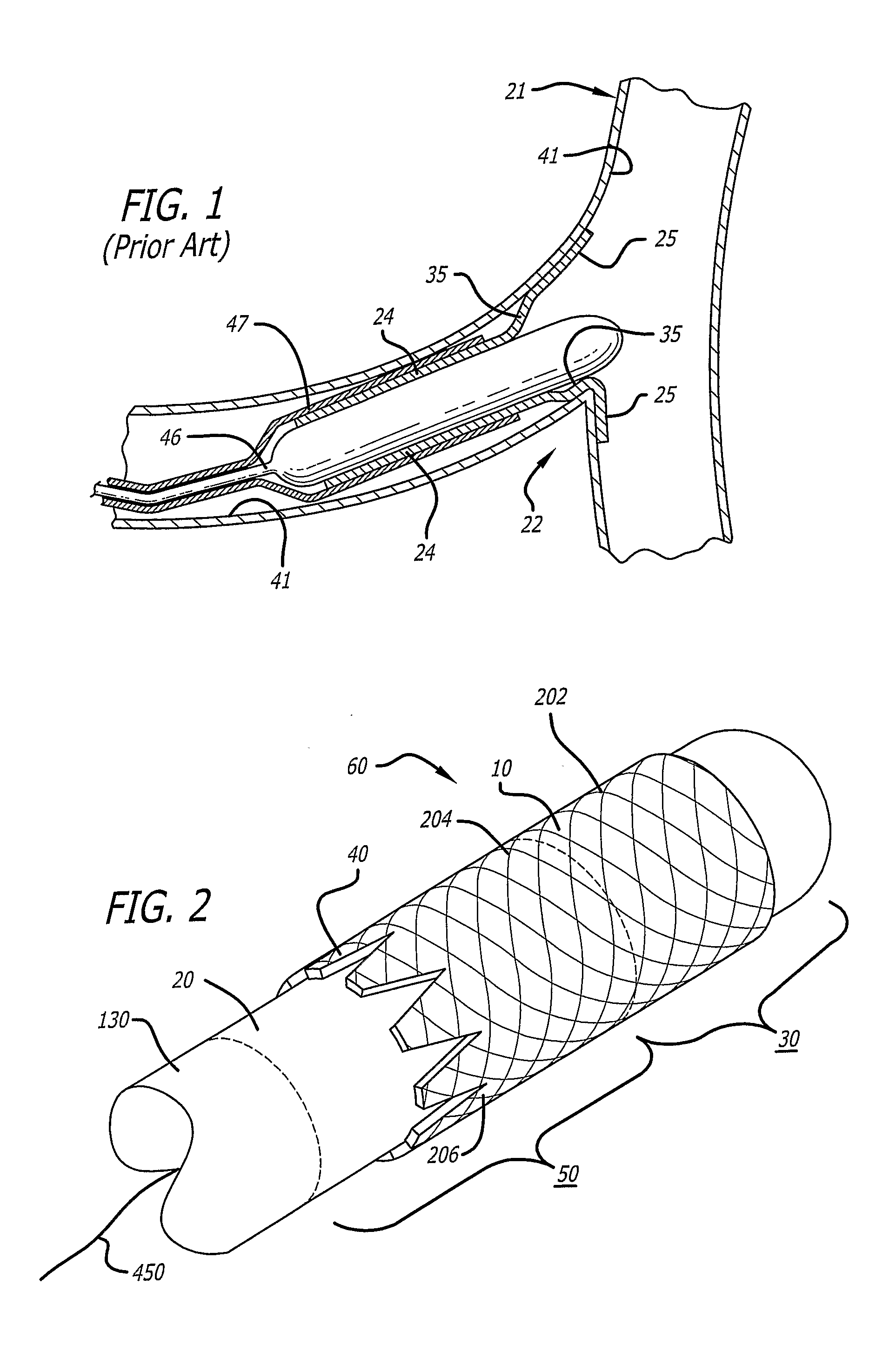
[0040]The phrases “main vessel” and “main artery” mean any vessel or duct within the body that has one or more branches extending off of it. The use of the term “main” may suggest that the “main artery” is more substantial or bigger than its branch or branches, however, this relationship is not required. A “main vessel” or “main artery” can be larger than, smaller than, or equal in size to its branches.

[0041]The term “branch” and the phrase “side branch” mean any vessel or duct within the body that finds its origination point at another vessel or duct within the body. A branch can be larger than, smaller than, or equal in size to its originating lumen.

[0042]The term “body” refers to the physical substance of a human or animal, living or dead.

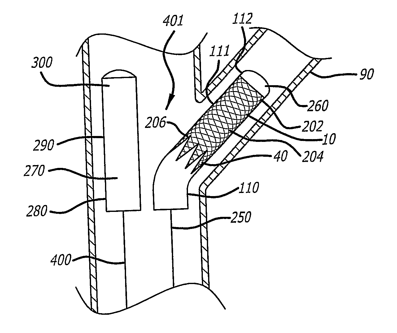
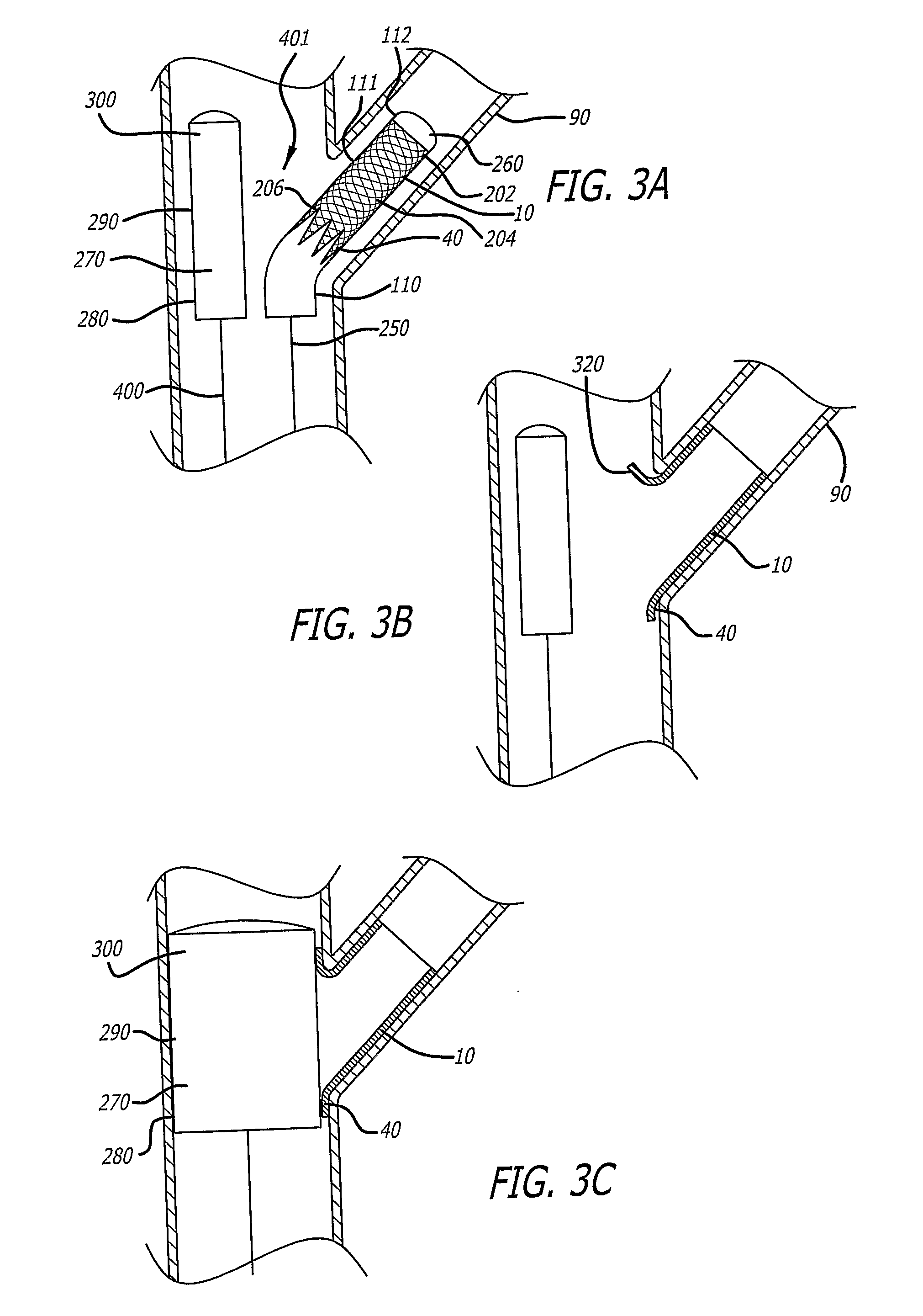
[0043]Previously-used stents did not provide a means to treat a lesion found primarily at an ostium and within the side branch of an artery when the branch could only be approached from the direction of the main artery (such as in the coronary a...


PUM

PropertyMeasurementUnit
elasticaaaaaaaaaa
bioactiveaaaaaaaaaa
pressuresaaaaaaaaaa

Abstract

Disclosed herein are proximally-flaring stents and balloon catheter systems and methods for using the same to restore patency to a side branch and its ostium at a vessel bifurcation, where the side branch can only be approached from the direction of the main artery. The system and methods include a proximally-flaring stent (10) and one or more balloon catheters (250, 400) with inflatable balloons that are able to push a flanged proximal portion (40) of the proximally-flaring stent entirely against the artery walls of the main artery of the side branch so that blood flow is not occluded.

Description

FIELD OF THE INVENTION[0001]The present invention relates to proximally-flaring stent and balloon catheter systems and methods for using the systems to restore patency to a side branch and its ostium at a vessel bifurcation where the side branch only can be approached in the direction of blood flow rather than in the direction opposite of blood flow (i.e. from the direction of the main artery). This invention also can be used for any ostium or any opening where an ostium must be approached from its main conduit (i.e., the duodenum and bile duct). Thus, the present invention can be used to approach any ostium or opening from its main conduit.BACKGROUND OF THE INVENTION[0002]Stents are ridged, or semi-ridged, tubular scaffoldings that are deployed within the lumen (inner tubular space) of a vessel or duct during angioplasty or related procedures intended to restore patency (openness) to vessel or duct lumens. Stents generally are left within the lumen of a vessel or duct after angiopl...

Claims


Application Information

Patent Timeline
Patent Type & Authority Applications(United States)
IPC IPC(8): A61F2/84A61F2/82B23P11/00A61F2/86
CPCA61F2/86A61F2/958A61F2002/821Y10T29/49826A61F2250/0067A61M25/1027A61F2230/0054A61F2250/0048A61F2/954A61F2250/0039A61M25/104A61M2025/1015A61M2025/1045A61M2025/1059
Inventor PATADIA, BIPIN C.
Owner PATADIA BIPIN C
Why Eureka
Try Eureka