Fuel cell
- Summary
- Abstract
- Description
- Claims
- Application Information
AI Technical Summary
Benefits of technology
Problems solved by technology
Method used
Image

Examples
first embodiment
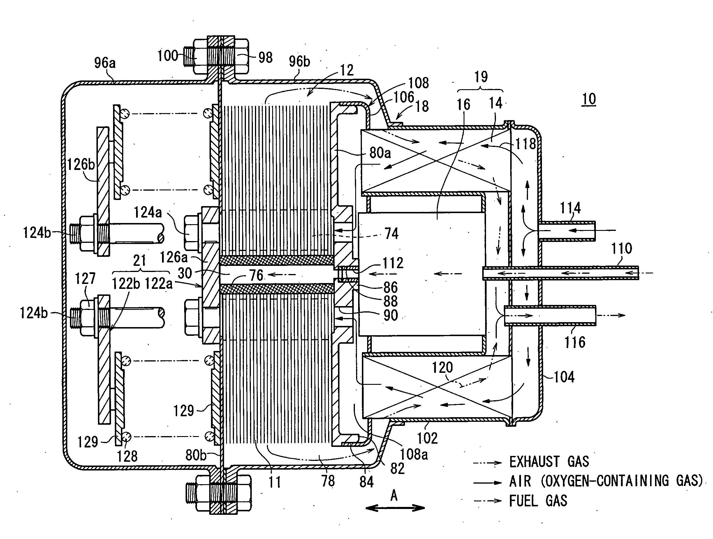
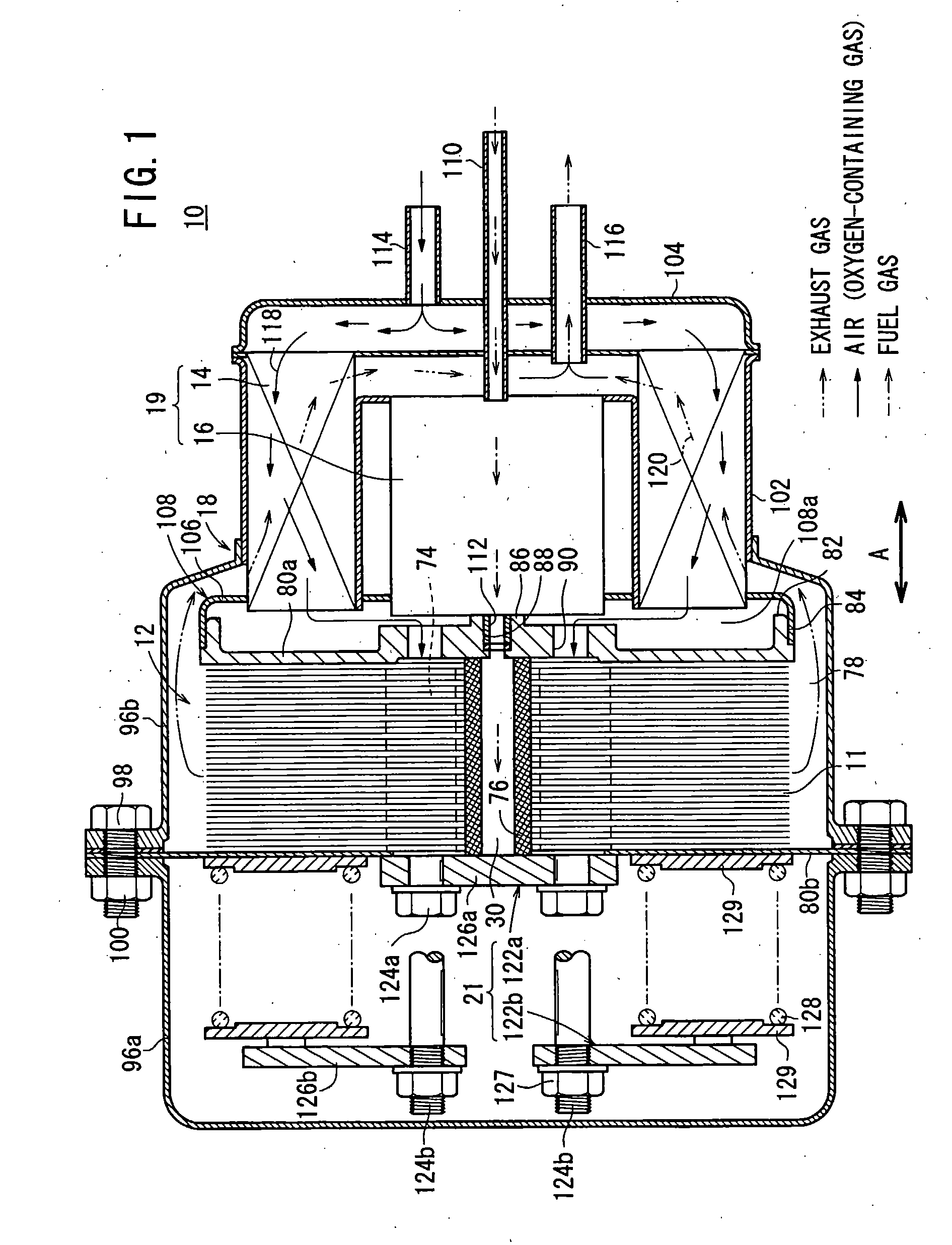
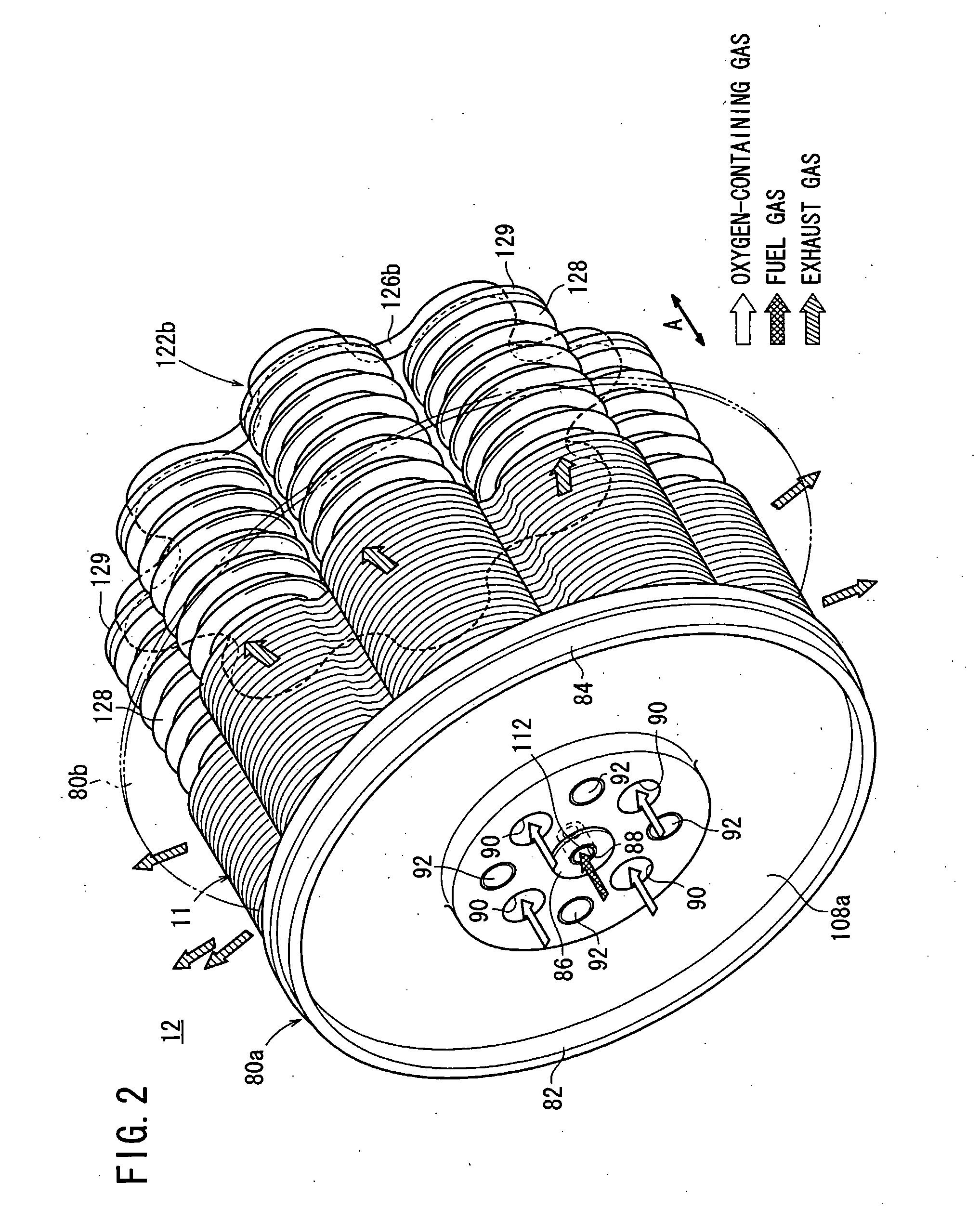
[0044]FIG. 1 is a partial cross sectional view showing a fuel cell system 10, including a fuel cell 11 according to the present invention. FIG. 2 is a perspective view schematically showing a fuel cell stack 12 formed by stacking a plurality of the fuel cells 11, in a direction indicated by the arrow A.
[0045]The fuel cell system 10 is used in various applications, including stationary and mobile applications. For example, the fuel cell system 10 may be mounted on a vehicle. As shown in FIG. 1, the fuel cell system 10 includes the fuel cell stack 12, a heat exchanger 14, a reformer 16, and a casing 18. The heat exchanger 14 heats an oxygen-containing gas before it is supplied to the fuel cell stack 12. The reformer 16 reforms fuel in order to produce a fuel gas. The fuel cell stack 12, the heat exchanger 14, and the reformer 16 are disposed within the casing 18.
[0046]In the casing 18, a fluid unit 19, including at least the heat exchanger 14 and the reformer 16, is disposed on one si...
second embodiment
[0109]In the second embodiment, the load in the stacking direction is efficiently transmitted through the protrusions 146 of the circular disk 36. Therefore, the fuel cells 140 can be stacked together with a small load, thereby reducing distortions in the electrolyte electrode assemblies 26 and the separators 142.
[0110]The protrusions 146 on the surface 36b of the circular disk 36 are formed by etching or the like as solid portions. Thus, the shape, positions, and density of the protrusions 146 can be changed arbitrarily and easily, depending on the flow state and / or fluidic conditions of the oxygen containing gas, whereby a desired flow of the fuel gas can be achieved. Further, since the protrusions 146 are formed as solid portions, the protrusions 146 cannot be deformed, and thus, the load is reliably transmitted through the protrusions 146, and electricity is collected efficiently through the protrusions 146.
third embodiment
[0111]FIG. 18 is a partial enlarged view showing a separator 160 of a fuel cell according to the present invention.
[0112]A fuel gas channel 164 for supplying the fuel gas to the anode 24 is formed on each of circular disks 162 of the separator 160. The fuel gas channel 164 includes a plurality of grooves 166a to 166h arranged in a serpentine pattern branching from the fuel gas inlet 38. In each of the serpentine grooves 166a to 166h, the groove width of the arc-shaped portions, which are provided concentrically substantially around the fuel gas inlet 38, increases gradually toward the outer circumferential portion of the surface of the anode 24. The width of the ridges 168a to 168h formed between the grooves also increases gradually toward the outer circumferential portion of the surface of the anode 24.
[0113]In the third embodiment, the same advantages as those of the first and second embodiments can be obtained. For example, a change in the leakage amount of the fuel gas that leak...
PUM
 Abstract
Description
Claims
Application Information
 - R&D
- Intellectual Property
- Life Sciences
- Materials
- Tech Scout
- Unparalleled Data Quality
- Higher Quality Content
- 60% Fewer Hallucinations
Browse by: Latest US Patents, China's latest patents, Technical Efficacy Thesaurus, Application Domain, Technology Topic, Popular Technical Reports.
© 2025 PatSnap. All rights reserved.Legal|Privacy policy|Modern Slavery Act Transparency Statement|Sitemap|About US| Contact US: help@patsnap.com