
Energy-dissipating element and shock absorber comprising an energy-dissipating element

a technology of energy-dissipating elements and shock absorbers, which is applied in the direction of elastic dampers, bumpers, vehicle components, etc., can solve the problems of only using about half of the overall length of the buffer, and the energy of deformation is destructively converted into heat and deformation energy, and achieves high energy dissipation

Inactive Publication Date: 2010-09-23
VOITH PATENT GMBH
View PDF0 Cites 4 Cited by
  • Summary
  • Abstract
  • Description
  • Claims
  • Application Information

AI Technical Summary

Benefits of technology

The present invention relates to an energy-dissipating element that can be used in various applications to absorb energy and reduce the space required for installation. The invention provides an energy-dissipating element that can plastically deform over a longer period of time when activated, allowing for a higher energy dissipation capacity. The invention also provides an energy-dissipating element that can be easily installed and connected to other components, both axially and radially. The invention further notes that the energy-dissipating element has a self-stabilizing characteristic, making it easier to absorb energy and predict the sequence of events during the energy dissipation process. The invention also notes that the energy-dissipating element can be insensitive to any imperfections in the material used for its production.

Problems solved by technology

When the break-off connections respond, the plunger moves toward the buffer housing, in consequence of which the buffer housing is plastically deformed such that the impact energy is destructively converted into the energy and heat of deformation.
The disadvantage in this is that, based on its design, this prior art solution can only make use of about half of the buffer's overall length when absorbing shock.
After the buffer housing deforms, it is in particular not possible in the known solution to have a further shortening in the longitudinal direction of the buffer, and thus nor a plastic deformation of the buffer housing.

Method used


Image

  • Energy-dissipating element and shock absorber comprising an energy-dissipating element
  • Energy-dissipating element and shock absorber comprising an energy-dissipating element
  • Energy-dissipating element and shock absorber comprising an energy-dissipating element

Examples


first embodiment

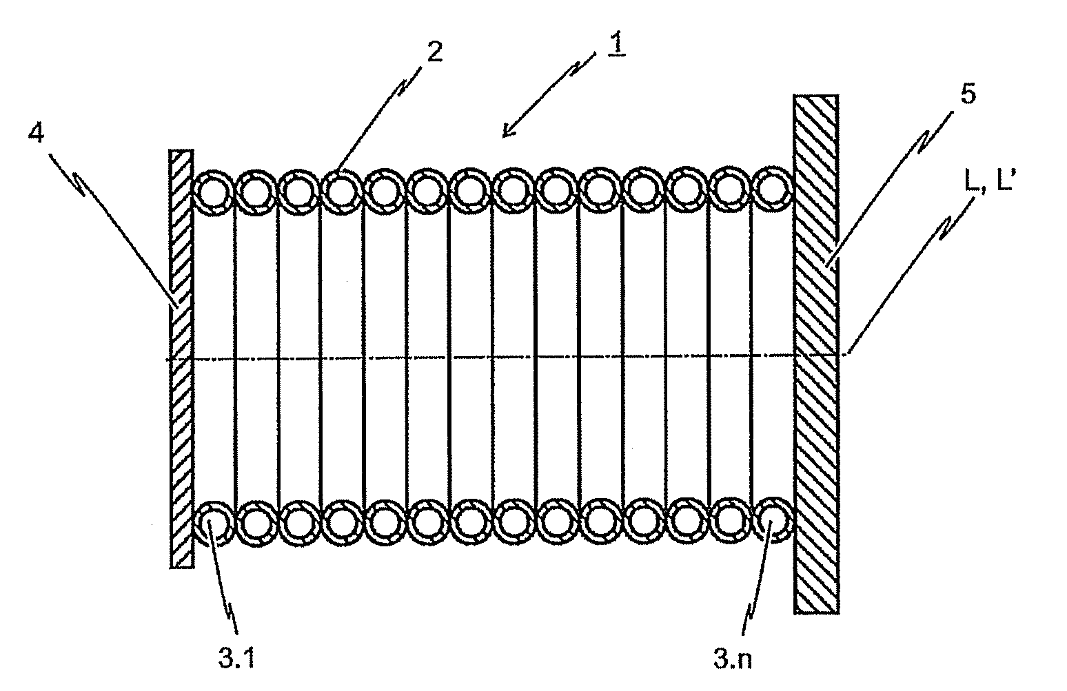
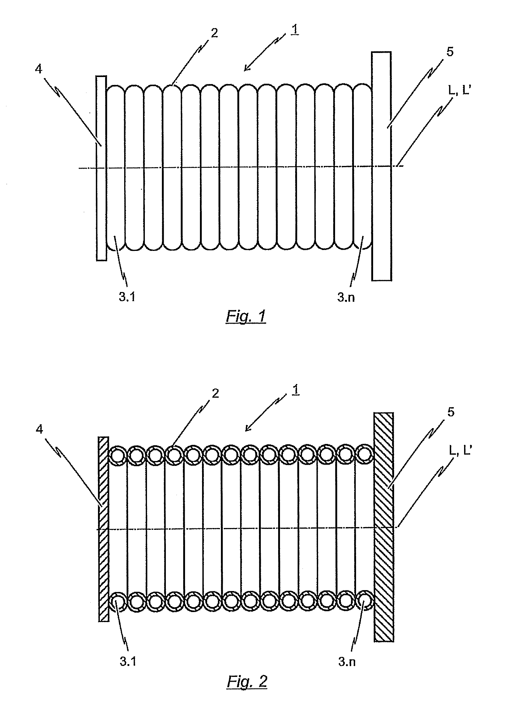
[0041]FIG. 1 depicts a side view of the inventive energy-dissipating element 1. The energy-dissipating element 1 is arranged between a force-transferring element 4 and a base plate 5 such that compressive forces introduced into the force-transferring element 4 will be transmitted over wall 2 of the energy-dissipating element 1 to the base plate 5. As depicted, the energy-dissipating element 1 is configured in the form of a hollow body extending in the longitudinal direction L. The peripheral surface of the hollow body is formed by the wall 2 of energy-dissipating element 1.

[0042]With the first embodiment of the inventive energy-dissipating element 1 is depicted in FIG. 1, the wall 2 of said energy-dissipating element 1 is formed by a plurality of toroidal deforma-tion elements 3.1 to 3.n. These toroidal deformation elements 3.1 to 3.n are arranged such that the rotational axis L′ of each toroidal deformation element 3.1 to 3.n corresponds to the longitudinal axis L of the hollow bod...

second embodiment

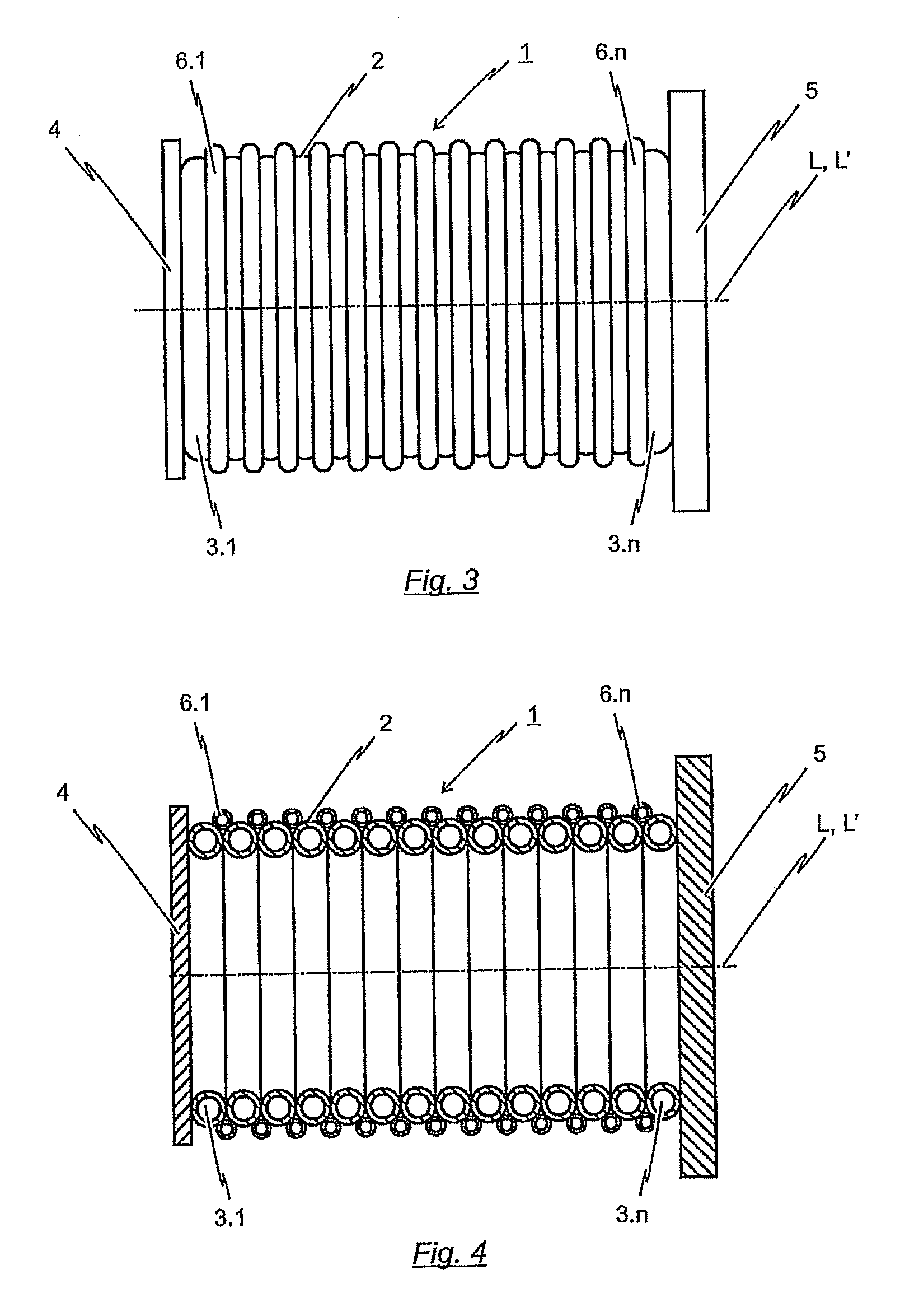
[0046]FIG. 3 shows a side view of the inventive energy-dissipating element 1. FIG. 4 is a longitudinally-sectioned representation of the energy-dissipating element 1 depicted in FIG. 3.

[0047]The second embodiment of the inventive energy-dissipating element 1 differs from the embodiment previously described with reference to the FIGS. 1 and 2 representations in that additionally to toroidal deformation elements 3.1 to 3.n, a plurality of auxiliary toroidal deformation elements 6.1 to 6.n are provided. These auxiliary toroidal deformation elements 6.1 to 6.n are likewise formed from a profile. The profile of the auxiliary deformation elements 6.1 to 6.n can have a cross-section which differs from the cross-section of the hollow profile used for the toroidal deformation elements 3.1 to 3.n. In the embodiment of the energy-dissipating element 1 depicted in FIGS. 3 and 4, the auxiliary toroidal deformation elements 6.1 to 6.n have a smaller cross-section than that of deformation elements...


PUM


Abstract

An energy-dissipating element has the form of a hollow body extending in the longitudinal direction, wherein the element comprises a wall forming the peripheral surface of the hollow body. The element is designed to respond upon the exceeding of a critical impact force applied to a front of the element and to convert at least a portion of the impact energy ensuing from the transfer of the impact force through the element into the energy and heat of deformation by plastic deformation. The energy-dissipating element is composed of at least one deformation element formed from a hollow profile and extending along the longitudinal axis of the hollow body which forms the wall of the energy-dissipating element.

Description

BACKGROUND OF THE INVENTION[0001]1. Field of the Invention[0002]The present invention relates to an energy-dissipating element in the form of a longitu-dinally-extending hollow body, wherein the energy-dissipating element comprises a wall forming the peripheral surface of the hollow body, and wherein the energy-dissipating element is designed to respond upon the exceeding of a critical impact force applied to a front end of said energy-dissipating element and to absorb at least a portion of the impact energy ensuing from the transfer of the impact force through the energy-dissipating element by plastic deformation; i.e. converting it to the energy and heat of deformation. The invention further relates to a shock absorber, in particular for use as a side buffer on the front end of a rail-bound vehicle such as e.g. a railroad vehicle, or for use in a buffer stop, wherein the shock absorber comprises an energy-dissipating is element of the type described above.[0003]Energy-dissipating ...

Claims


Application Information

Patent Timeline
Patent Type & Authority Applications(United States)
IPC IPC(8): B60R19/24
CPCB60R19/34F16F7/12B61G11/16
Inventor BEIKA, UWEDROBEK, STEFFEN
Owner VOITH PATENT GMBH
Learn More