
Device and network system

a network and device technology, applied in the direction of data switching networks, line-transmission details, power feeding arrangements, etc., can solve the problems of troublesome communication port configuration and the inability to receive electric power through power feeding communication ports

Active Publication Date: 2010-09-16
ORMON CORP
View PDF4 Cites 16 Cited by
  • Summary
  • Abstract
  • Description
  • Claims
  • Application Information

AI Technical Summary

Benefits of technology

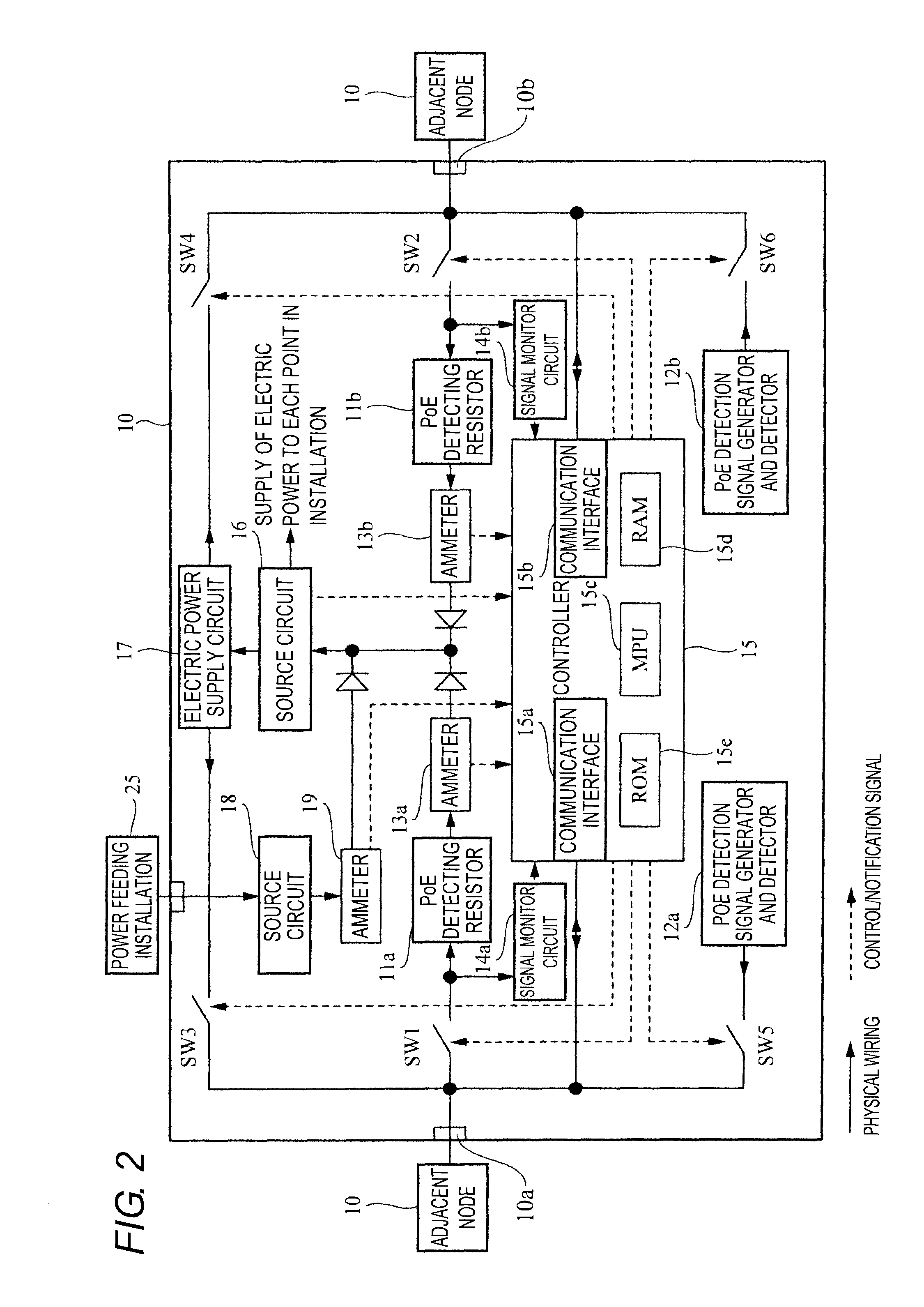
The present invention relates to a device that can be connected to a network and has multiple power ports. The device includes a control unit that can switch the power ports into a power receiving state even if the device is not connected to any power port initially. This allows for flexible and automatic determination of the power supply pathway based on the network configuration. The device can also have an electric power supply unit that uses part of the supplied electric power for power feeding to another device connected to the network. The power feeding can be performed through the same network port that receives the electric power, or through another port. The device can detect the electric power needed for another device and flexibly correspond to the situation. The power port can be a communication port that conducts data communication, and the network can transmit the data and electric power simultaneously. The invention also includes a network system in which multiple devices are connected through a network, and the device can sequentially supply electric power to another device. The invention allows for flexible and automatic determination of the power supply pathway based on the network configuration.

Problems solved by technology

Unfortunately configuration of the communication port becomes troublesome because the function of each communication port is previously determined.
Further, the supply of electric power cannot be received by utilizing the power feeding communication port, even if the communication port configured for the power feeding is vacant in case of trouble with the power receiving communication port or the network cable connected to the power receiving communication port.

Method used


Image

  • Device and network system
  • Device and network system
  • Device and network system

Examples


Embodiment Construction

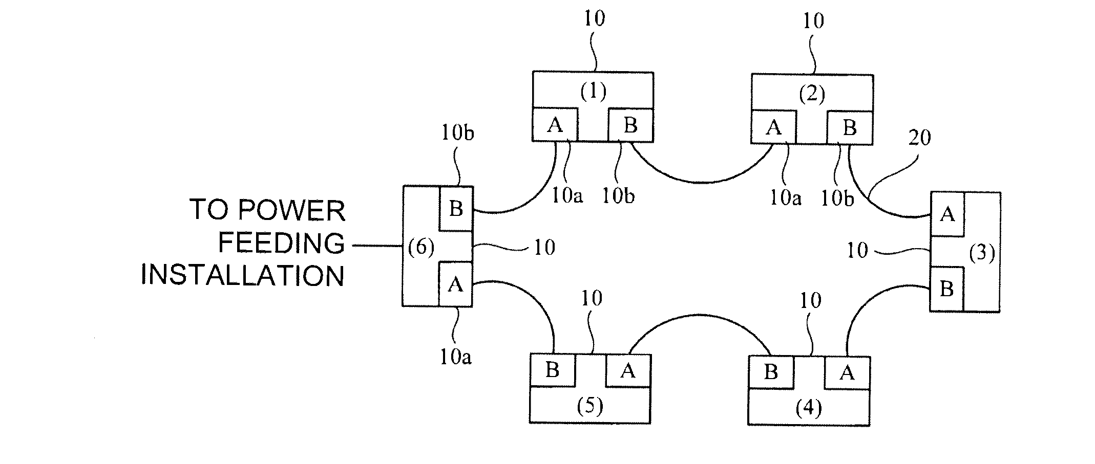
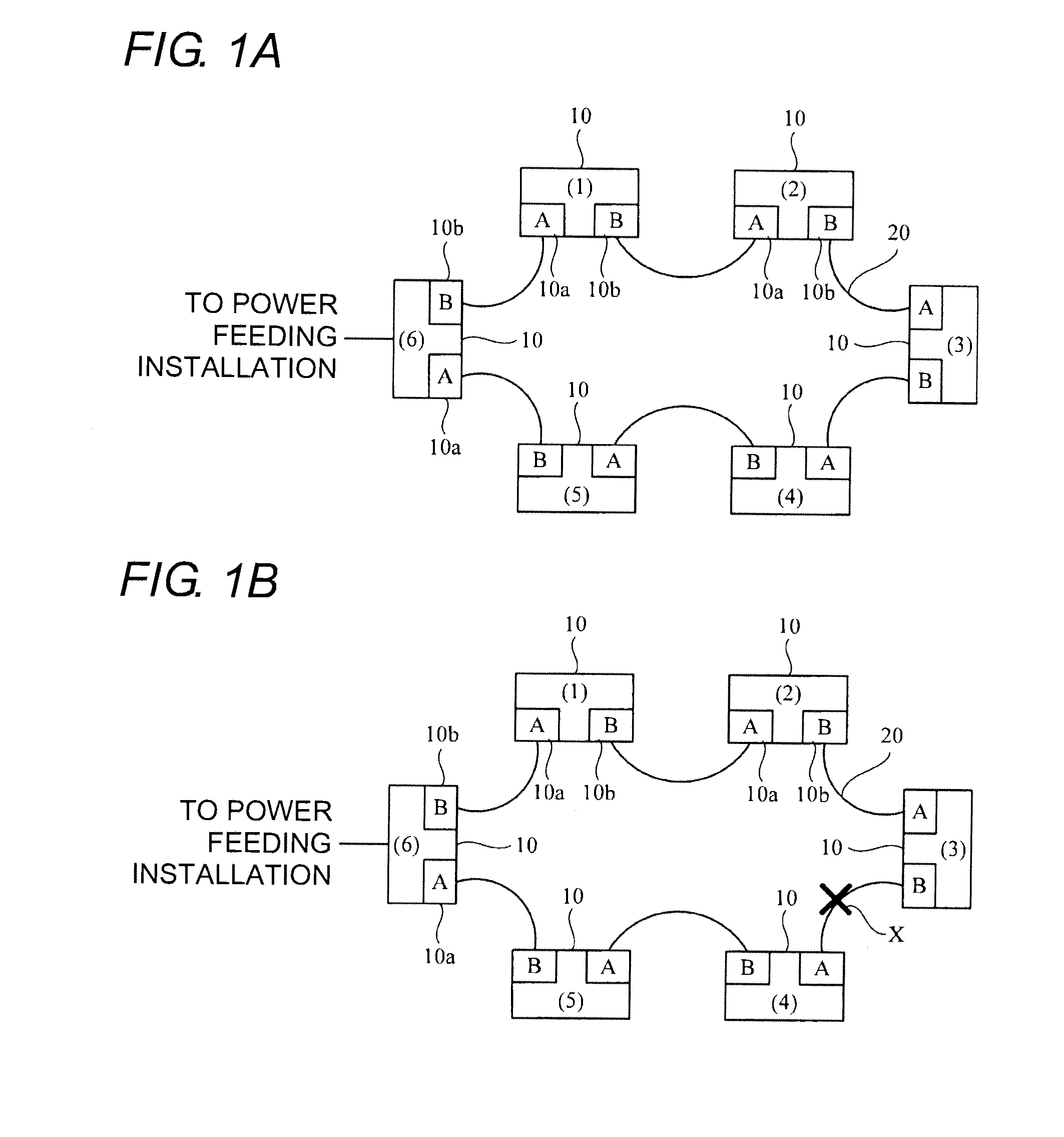
[0024]FIG. 1 illustrates an example of a network system. In a configuration of the network system, devices 10 each of which has plural communication ports (in the embodiment, a first communication port 10a and a second communication port 10b) are wired into a ring shape through a network cable 20. That is, the communication ports of adjacent devices 10 are connected through the network cable 20. The device 10 is pursuant to Ether CAT (registered trademark: Ethernet for Control Automation Technology) that is one of industrial network standards. The Ether CAT (registered trademark) is a high-speed field bus system based on the Ethernet (registered trademark).

[0025]In the ring connection mode, for example, even if the network cable 20 is disconnected at one point (point X in FIG. 1B) as illustrated in FIG. 1B, the data communication can be continued through another pathway. Accordingly, the device 10 has a function of monitoring where the network cable 20 is disconnected and a function...


PUM

PropertyMeasurementUnit
electric poweraaaaaaaaaa

Abstract

In a device according to one aspect of the invention, plural communication ports switch appropriately between a power receiving port and a power feeding port, thereby dealing with supply of electric power through a network in various network configurations. Plural devices are connected to a network cable to form a network system. In an initial state before power receiving, all plural communication ports of the device are put in to a power receiving enabling state. When the electric power is supplied from one of the communication ports, other communication ports are put into a power receiving disabling state. The device feeds part of the received electric power to another adjacent device by utilizing the communication port put into the power receiving disabling state. The supply of electric power can sequentially be performed from the device that receives the supply of electric power from an external power feeding installation to an adjacent device, and finally all the devices receive the supply of electric power through the network.

Description

BACKGROUND OF THE INVENTION[0001]This application is based on Japanese Patent Application No. 2009-058007 filed with the Japan Patent Office on Mar. 11, 2009, the entire content of which is hereby incorporated by reference.[0002]1. Technical Field[0003]The present invention relates to a device constituting a network and a network system, more particularly to an improved technology concerting supply of electric power to the device through the network.[0004]2. Related Art[0005]PoE (Power over Ethernet (registered trademark)) is a technology for supplying the electric power by utilizing an Ethernet (registered trademark) cable. The use of PoE can facilitate the supply of electric power to the device installed in the site the electric power is hardly directly supplied. In PoE, because both the data and the electric power can be transmitted through the cable, it is not necessary to separately wire the cable for data communication and the cable for supply of electric power, and the wiring...

Claims


Application Information

Patent Timeline
Patent Type & Authority Applications(United States)
IPC IPC(8): G06F1/18
CPCH04B3/44H04L12/42H04L12/40045H04L12/10
Inventor TOGAWA, SATOSHI
Owner ORMON CORP
Learn More