Grating-based sensor combining label-free binding detection and fluorescence amplification and readout system for sensor
a biochemical sensor and label-free binding technology, applied in the direction of fluorescence/phosphorescence, optical radiation measurement, spectrophotometry/monochromators, etc., can solve the problems of insufficient surface area (depth) of prior er gratings, inability to properly control, and inability to induce an unacceptable source of variation, etc., to facilitate the study of very tight binding interactions and enhance the effect of quenching
- Summary
- Abstract
- Description
- Claims
- Application Information
AI Technical Summary
Benefits of technology
Problems solved by technology
Method used
Image
Examples
first embodiment
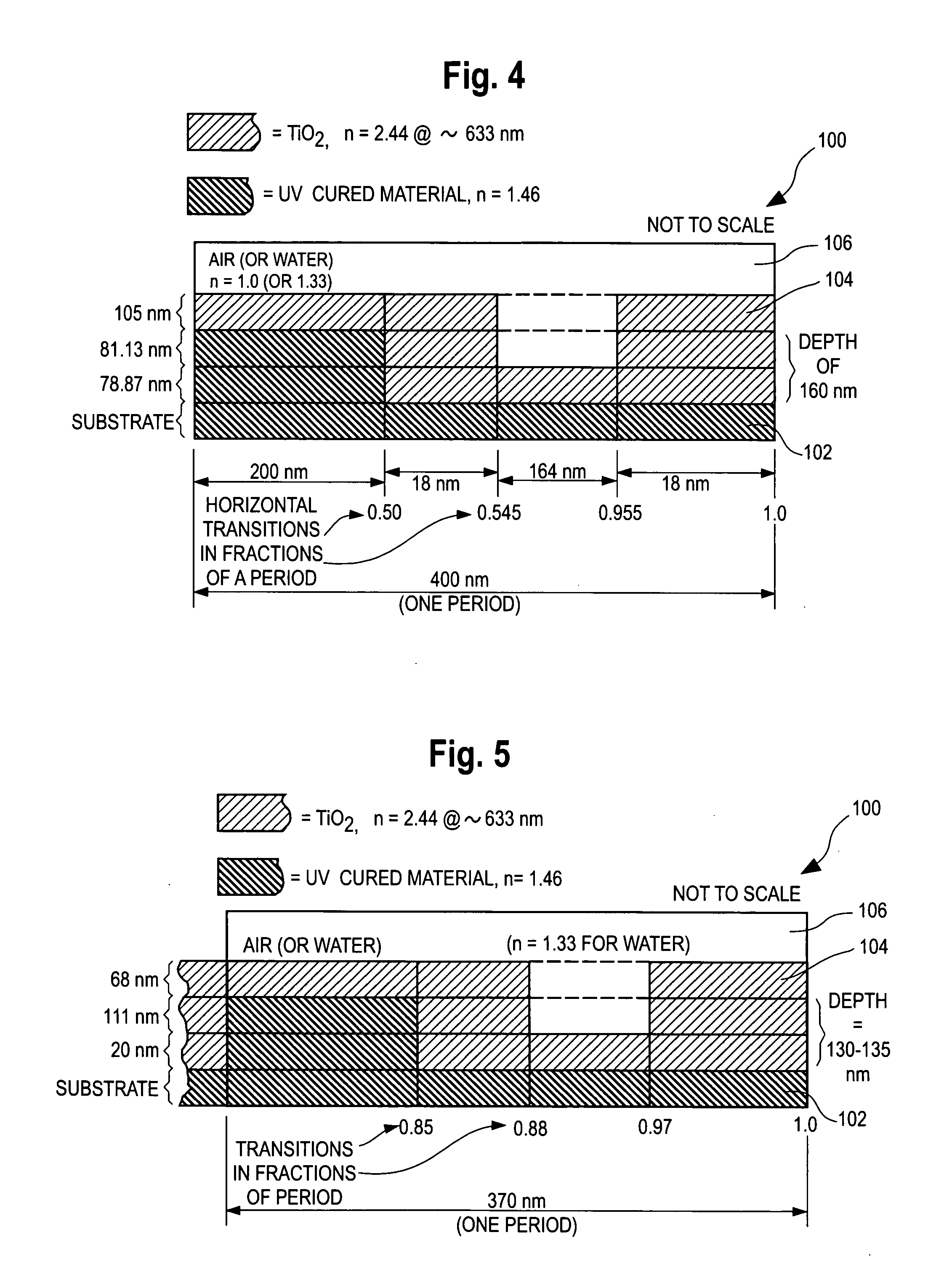
[0089]FIG. 4 is a schematic cross-sectional illustration of a first embodiment of a one-dimensional sensor having a grating structure 100 that is expected to meet commercial requirements for both ER and label-free applications of a grating-based sensor. FIG. 4 shows one period of a grating structure 100 in one dimension or direction. The dimensions are not to scale in FIG. 4.
[0090]The grating 100 of FIG. 4 is superimposed and bonded to a base sheet of clear material such as Polyethylene Terepthalate (PET) or other plastic, glass or other material (not shown).
[0091]The grating structure consists of a periodically repeating material 102 which preferably comprises a UV-cured material, e.g., epoxy, applied with the aid of a grating master wafer (not shown) to replicate the grating pattern onto the base sheet of PET material located below the layer “substrate.” The UV cured material 102 is applied to a substrate sheet such as PET. Substrate materials can also include polycarbonate or cyc...
second embodiment
[0100]FIG. 5 is a cross-section of a second embodiment, showing one period of the grating structure in one dimension and the structure of the of the UV cured layer 102, the high index of refraction layer 104, and the sample medium 106. The dimensions and transition points are as shown in the drawing. The drawing is not to scale.
[0101]The design of FIG. 5 differs from that of FIG. 4 is several respects:
[0102]a) It has a shorter grating period.
[0103]b) It has narrower grating troughs or recesses. The “duty cycle” (percentage of the grating at the upper level in a unit cell) is 88% in FIG. 5 (0 to 0.85 and 0.97 to 1.0). Narrow troughs with duty cycles of between 70 and 95% are exemplary of the narrow trough embodiments. The narrow troughs generally give better label-free detection results. The narrow trough feature narrows the TE resonance peak, thus indicating increased field strength. While practical use of the ER effect requires a sufficiently broad resonance, a resonance with exces...
PUM
| Property | Measurement | Unit |
|---|---|---|
| depth | aaaaa | aaaaa |
| depth | aaaaa | aaaaa |
| depth | aaaaa | aaaaa |
Abstract
Description
Claims
Application Information
 - R&D
- Intellectual Property
- Life Sciences
- Materials
- Tech Scout
- Unparalleled Data Quality
- Higher Quality Content
- 60% Fewer Hallucinations
Browse by: Latest US Patents, China's latest patents, Technical Efficacy Thesaurus, Application Domain, Technology Topic, Popular Technical Reports.
© 2025 PatSnap. All rights reserved.Legal|Privacy policy|Modern Slavery Act Transparency Statement|Sitemap|About US| Contact US: help@patsnap.com


