Eureka AIR delivers breakthrough ideas for toughest innovation challenges, trusted by R&D personnel around the world.

Apparatus and method for generating steam

a technology of steam generator and steam generator, which is applied in the direction of mechanical equipment, fixed capacity gas holders, lighting and heating apparatus, etc., can solve the problems of time-consuming and labor-intensive cleaning of the boiler after waiting for the boiler to cool down, endangering the user, and reducing so as to reduce the heating power and reduce the heating power emitted into the boiler. , the effect of fast and simple adaptation

Inactive Publication Date: 2010-09-09
KONINKLIJKE PHILIPS ELECTRONICS NV
View PDF5 Cites 5 Cited by
  • Summary
  • Abstract
  • Description
  • Claims
  • Application Information

AI Technical Summary

Benefits of technology

The invention is a steam generating apparatus with a boiler for receiving water to be heated, an opening in the boiler for adding water, and a steam duct for conducting steam to a steam applying means. The apparatus includes a by-pass duct that can be opened to safely discharge steam from the boiler without leaving any pressure inside. The opening can be closed using a closing means, and the by-pass duct can be opened to release steam from the boiler during normal operation. The invention also includes a water filling means for manually adding water to the boiler, which has a cross section that is smaller than the boiler inlet end to prevent water splashing out during the filling process. The water filling means can be made of one piece or multiple components. The technical effects of the invention include improved safety and efficiency in generating steam.

Problems solved by technology

The supply of water to be vaporized in steam generating apparatuses may be provided by a water reservoir, thus allowing for a limited autonomy in certain household appliances.
These designs raise a number of disadvantages and hazards for the user: Refilling or cleaning the boiler after waiting for the boiler to cool down is time consuming.
This hot steam endangers the user.
This undesirably generated steam escapes through the opening in the boiler.
In these situations he frequently experiences water splashing out of the boiler opening.

Method used


Image

  • Apparatus and method for generating steam
  • Apparatus and method for generating steam
  • Apparatus and method for generating steam

Examples


Embodiment Construction

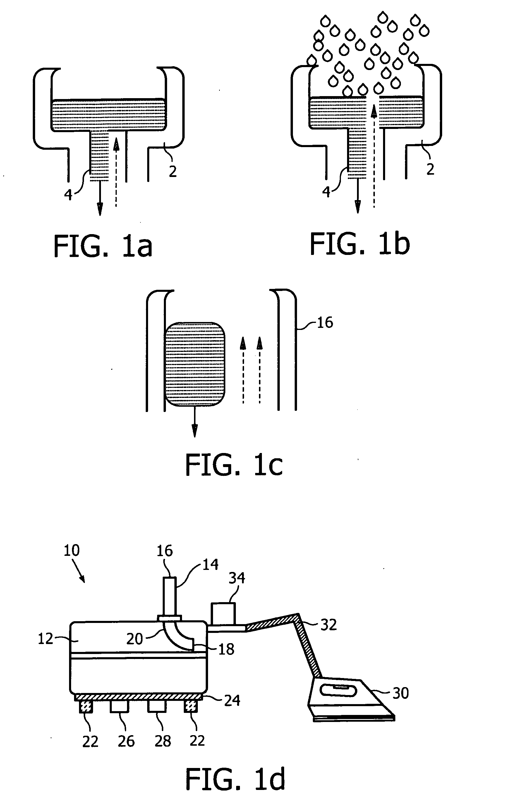
[0038]FIGS. 1a and 1b illustrate the situation of water refilling in steam generating apparatuses according to the state of the art. When the water reservoir of the steam generating apparatus is emptied during operation, the inner surfaces of the boiler (shell, heating plate; not shown) are usually still hot, when the user is beginning to refill water. To facilitate the refilling, a cup-shaped or funnel-shaped water inlet 2 is provided. The user usually wants to minimize the time required for the refilling process and tries to pour as much water as possible. Due to the cup-shaped form of the water inlet 2 and the narrower inner diameter of the pipe 4 leading to the boiler, the water inlet 2 is initially completely filled with water. The cold water being poured in gets in contact with the hot inner surfaces of the boiler and evaporates immediately. This undesirably generated steam escapes through the water filling inlet pipe. This situation is shown in FIG. 1a, where the water being ...


PUM

PropertyMeasurementUnit
inner diameteraaaaaaaaaa
steam pressureaaaaaaaaaa

Abstract

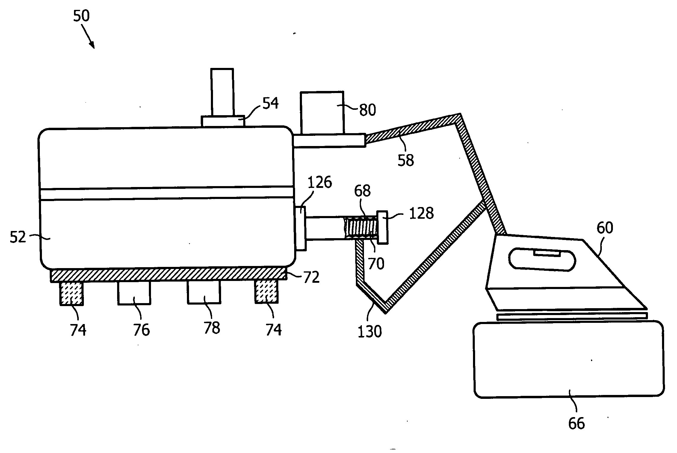
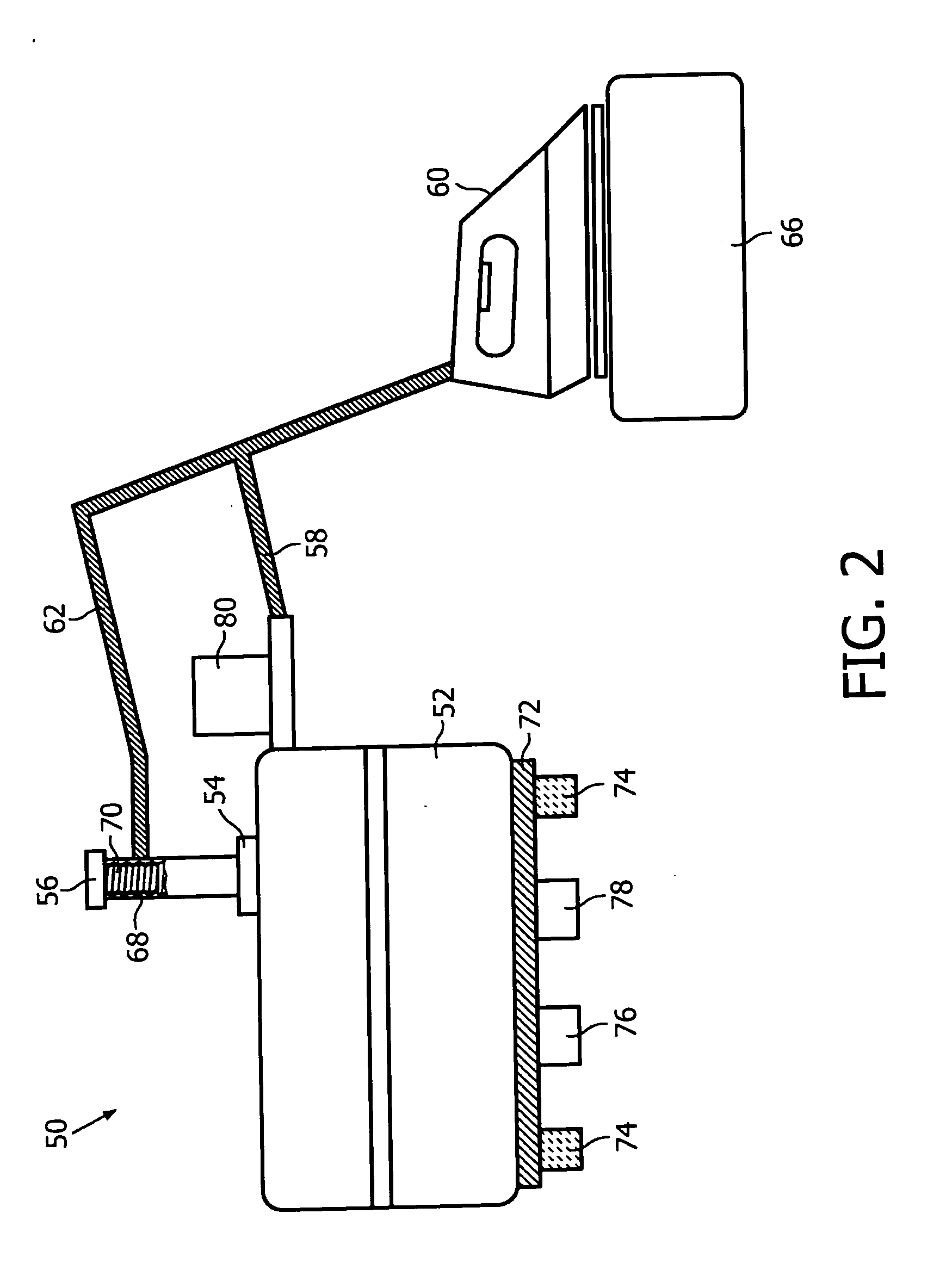
The present invention relates to a steam generating apparatus (50) comprising a boiler (52) for receiving water to be heated, an opening (54, 126) in a wall of the boiler, the opening being closable by closing means (56, 128, 136), and a steam duct (58) for conducting steam generated in the boiler (52) to steam applying means (60), wherein a by-pass duct (62, 130) by-passing the steam duct (58) is provided for discharging steam from the boiler (52) to the steam applying means (60). The present invention further relates to a method of operating a steam generating apparatus (50).

Description

FIELD OF THE INVENTION[0001]The present invention generally relates to steam generating apparatuses and to a method of operating a steam generating apparatus. In particular, the invention relates to steam generating apparatuses with a limited or unlimited water reservoir.BACKGROUND OF THE INVENTION[0002]The supply of water to be vaporized in steam generating apparatuses may be provided by a water reservoir, thus allowing for a limited autonomy in certain household appliances. The water stored for an operation cycle is heated by heating means in a boiler. The generated steam can be applied without the need of the steam generating apparatus being coupled permanently to a permanent water supply, e.g. a water conduit. In consequence, the steam generating apparatus, i.e. its water reservoir, has to be refilled regularly. Therefore, a water-filling opening for (re-) filling the boiler manually after each operation cycle is provided. The water-filling inlet commonly is cup-shaped to allow ...

Claims


Application Information

Patent Timeline
Patent Type & Authority Applications(United States)
IPC IPC(8): D06F75/12D06F75/00
CPCD06F75/12F22B1/284F16J13/24
Inventor CHADHA, JASMEET SINGHJANAKIRAMAN, CHANDRA MOHANTHIRUMAZHISAI SANKARALINGAM, TAMILSELVATIEW, HOCK SOONCHING, BOON KHIANJIANG, YONG
Owner KONINKLIJKE PHILIPS ELECTRONICS NV
Why Eureka
Eureka Blog
Learn More