Quick change tool bit holder
- Summary
- Abstract
- Description
- Claims
- Application Information
AI Technical Summary
Benefits of technology
Problems solved by technology
Method used
Image
Examples
Embodiment Construction
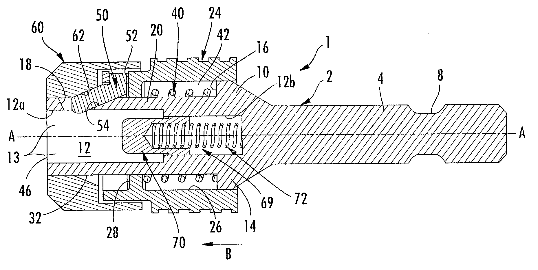
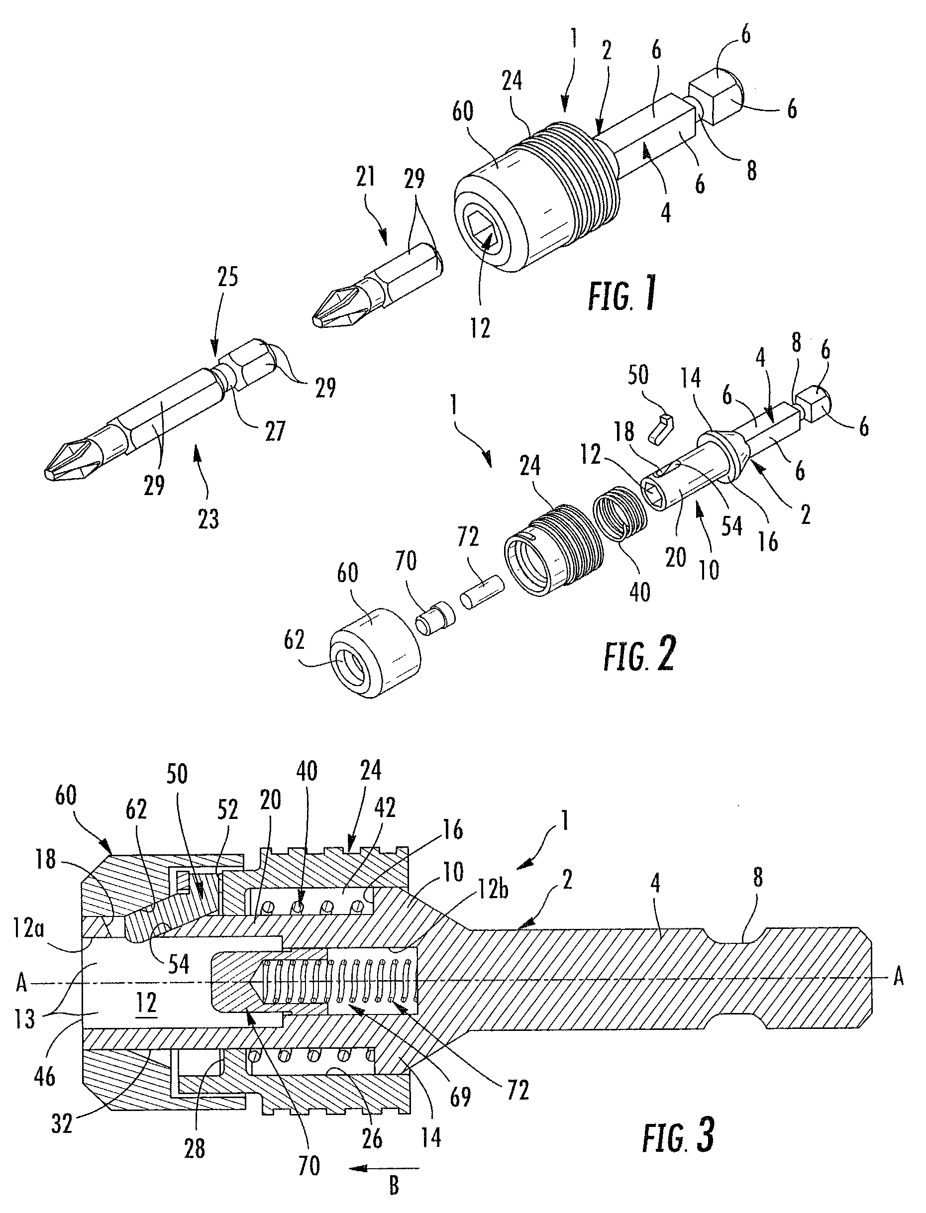
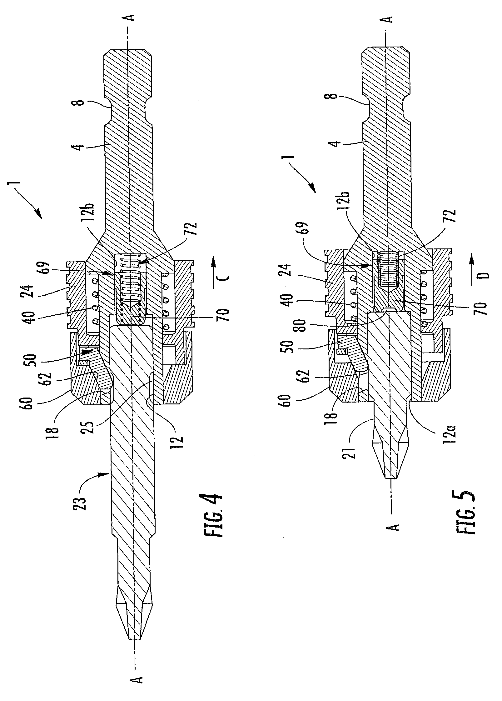
[0011]Referring to the figures, the quick change holder of the invention 1 includes a central hub 2 having a shank 4 that is to be inserted into the chuck of a rotary tool such as a drill, screw driver, power driver or the like. The shank 4 has a plurality of flat faces 6 and an annular groove 8 that provide a quick change coupling with a standard chuck. Formed on the central hub 2 opposite to the shank 4 is a head 10 having an internal bore 12. The internal bore 12 comprises a first larger diameter bore 12a that opens to the end 46 of the head 10 opposite shank 4 and a second smaller diameter bore 12b that extends from the first bore 12a toward the shank 4. Larger diameter bore 12a may include a plurality of flat faces 13 that are coextensive with flat faces 29 on the tool bits to prevent relative rotation between the holder 1 and the tool bit. Typically, the faces 13 of bore 12a create a hex shaped bore. The bit is inserted into bore 12a along the longitudinal axis A-A with the lo...
PUM
| Property | Measurement | Unit |
|---|---|---|
| Angle | aaaaa | aaaaa |
| Force | aaaaa | aaaaa |
| Angle | aaaaa | aaaaa |
Abstract
Description
Claims
Application Information
 - R&D
- Intellectual Property
- Life Sciences
- Materials
- Tech Scout
- Unparalleled Data Quality
- Higher Quality Content
- 60% Fewer Hallucinations
Browse by: Latest US Patents, China's latest patents, Technical Efficacy Thesaurus, Application Domain, Technology Topic, Popular Technical Reports.
© 2025 PatSnap. All rights reserved.Legal|Privacy policy|Modern Slavery Act Transparency Statement|Sitemap|About US| Contact US: help@patsnap.com


