Power demand management method and system
a technology of power demand and management method, applied in emergency power supply arrangements, instruments, electric devices, etc., can solve the problems of inaccurate process and little flexibility in monitoring and modifying multiple power systems
- Summary
- Abstract
- Description
- Claims
- Application Information
AI Technical Summary
Benefits of technology
Problems solved by technology
Method used
Image
Examples
example 1
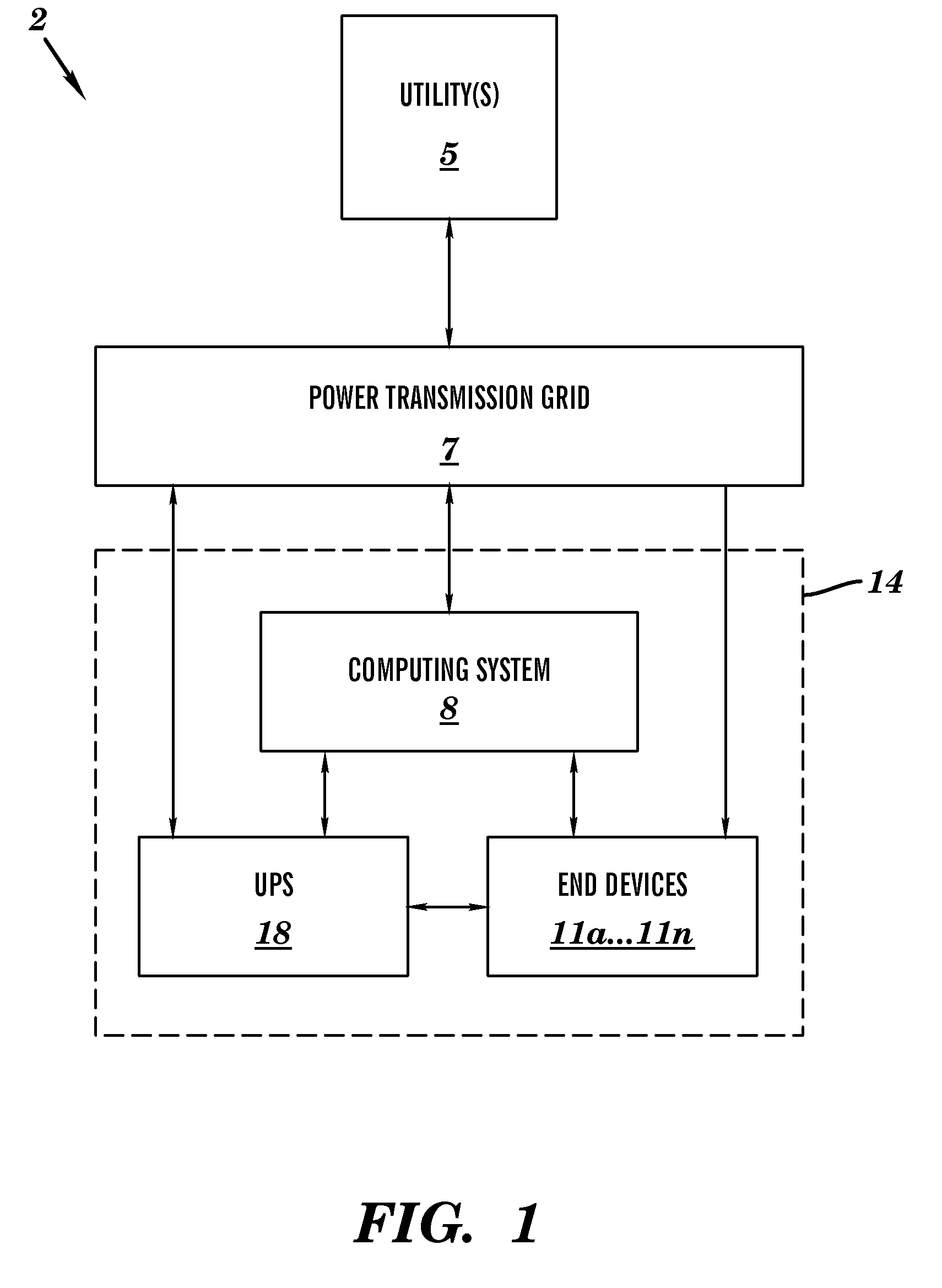
[0039]Example 1 describes a single-ended frequency responsive UPS (e.g., UPS 18 of FIG. 1). In this example, a 10 Kilowatt (KW) UPS with a 5 KW hour capacity is configured to generate supporting power starting at 59.95 HZ at 50% of capacity or a 5 KW output, increasing to 100% of capacity at 59.9 HZ. A standby battery threshold is set to a 100% state of charge and a cutout threshold is set to a 75% state of charge resulting in a difference equal to a 25% state of charge or 1.25 KW hours. Therefore, a maximum run-time at 50% output is 15 minutes and a maximum run-time at 100% output is 7.5 minutes. The following scenarios are described with respect to example 1.
Scenario 1
[0040]At 2:00 pm, a power transmission grid (e.g., power transmission grid 7) connected to a UPS (e.g., UPS 18) experiences a significant generator loss and a (grid interconnect) frequency falls to 59.9 Hz. The UPS immediately begins producing 100% of the required power. Downstream devices (e.g., end devices 11a . . ...
example 2
[0042]Example 2 describes a double-ended frequency responsive UPS (e.g., UPS 18 of FIG. 1). In this example, a 10 KW UPS with a 5 KW hour capacity is configured to generate supporting power starting at 59.95 Hz at 50% of capacity or 5 KW output, increasing to 100% of capacity at 59.9 Hz. A standby battery threshold is set to 90% state of charge (this allows up to 0.5 KWH to be consumed to offset over-frequency events) and a cutout threshold is set to 75% state of charge resulting in a difference equal to a 15% state of charge or 0.75 KW hours. Therefore, a maximum run-time at 50% output is 9 minutes and a maximum run-time at 100% output is 4.5 minutes.
[0043]The following scenarios are described with respect to example 2.
Scenario 1
[0044]At 2:00 pm, a power transmission grid (e.g., power transmission grid 7) connected to a UPS (e.g., UPS 18) experiences a significant generator loss and the (grid interconnect) frequency falls to 59.9 Hz. The UPS immediately begins generating 100% of th...
PUM
 Abstract
Description
Claims
Application Information
 - R&D
- Intellectual Property
- Life Sciences
- Materials
- Tech Scout
- Unparalleled Data Quality
- Higher Quality Content
- 60% Fewer Hallucinations
Browse by: Latest US Patents, China's latest patents, Technical Efficacy Thesaurus, Application Domain, Technology Topic, Popular Technical Reports.
© 2025 PatSnap. All rights reserved.Legal|Privacy policy|Modern Slavery Act Transparency Statement|Sitemap|About US| Contact US: help@patsnap.com


