
Stabilizing mechanism for ladders

Inactive Publication Date: 2010-08-26
GUINOVART RUBEN +1
View PDF27 Cites 20 Cited by
  • Summary
  • Abstract
  • Description
  • Claims
  • Application Information

AI Technical Summary

Problems solved by technology

But in crowded areas, such as with urban utility poles, the space is limited.
None of them, however, includes a mechanism that can be readily actuated.
The parent application provides for a similar mechanism but it lacks stability for some applications.
Schwenket and Cinquemani's application fails to disclose a locking system that is remotely actuated allowing the user to securely engage the ladder to the supporting surface while safely on the ground.
In addition, the related reference does not teach of arms that are rotably able to move in order to provide engagements to other supporting surfaces (such as a roof or parapet wall).

Method used


Image

  • Stabilizing mechanism for ladders
  • Stabilizing mechanism for ladders
  • Stabilizing mechanism for ladders

Examples


Embodiment Construction

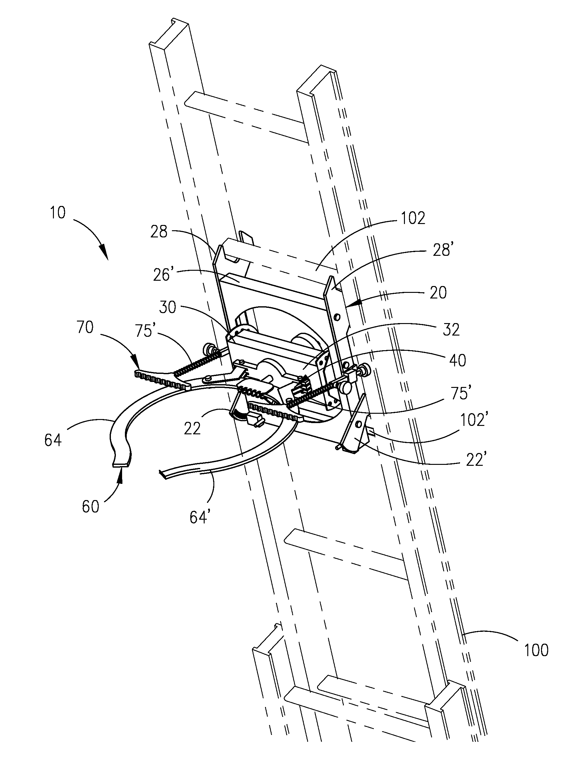
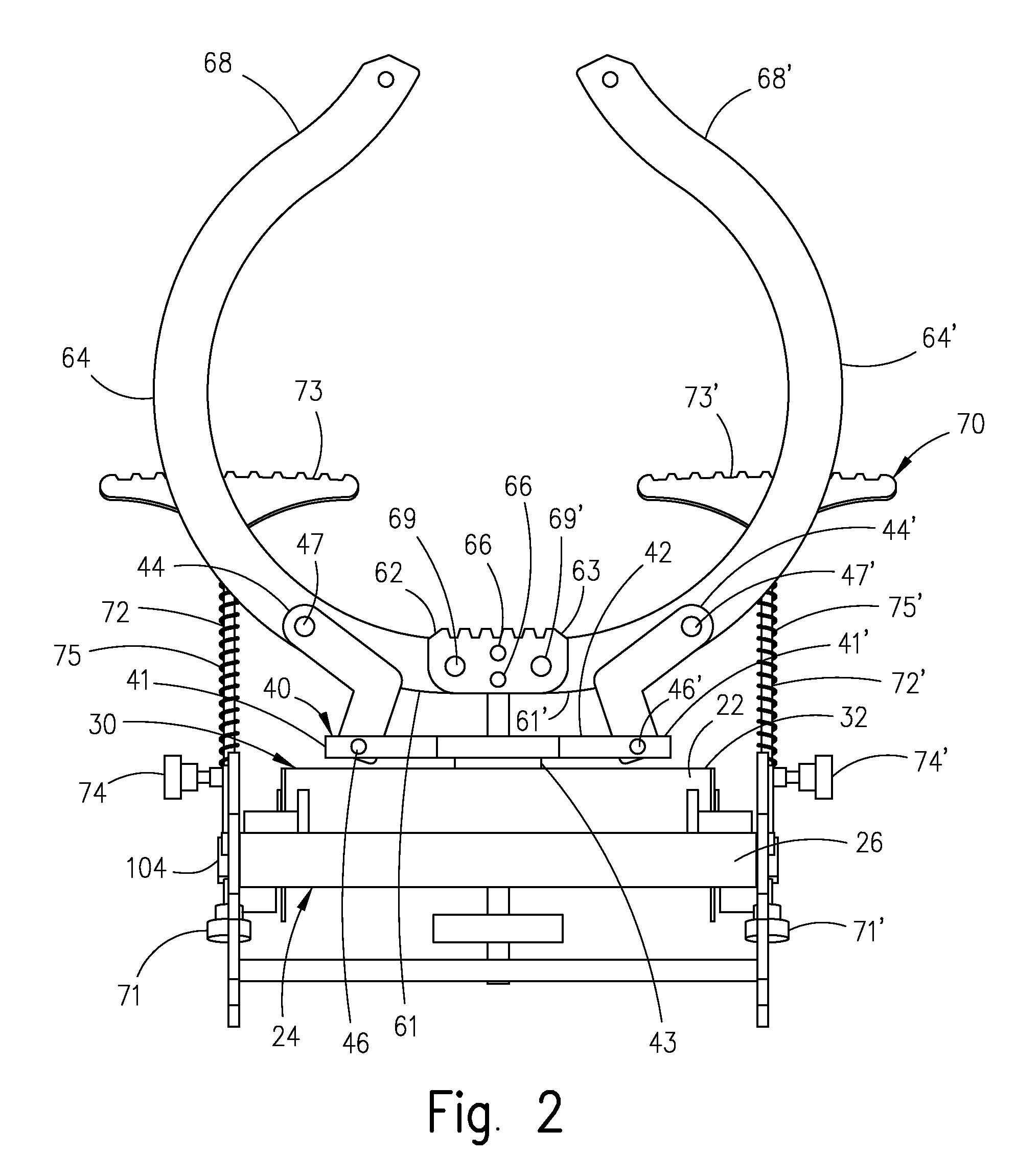
[0022]Referring now to the drawings, where the present invention is a mechanism generally referred to with numeral 10, it can be observed that it basically includes anchorage assembly 20, rotable housing assembly 30, linkage assembly 40, supporting arms assembly 60, stabilizing pad assembly 70, and locking assembly 80 (as best seen in FIG. 3). Mechanism 10 is removably mounted to a ladder 100, as seen in FIG. 1.

[0023]Anchorage assembly 20 is as best seen in FIG. 1 preferably mounted on ladder 100 at a predetermined distance from one end and the other end resting on a supporting and substantially horizontal surface (not shown). Anchorage assembly 20, as seen in FIGS. 2 and 3, includes frame assembly 24 which in turn includes longitudinal elongate members 25; 25′, which are kept at a parallel and spaced apart relationship with respect to each other by transversal elongate members 26; 26′ and transversal plate 27 including central aperture 27′. In one of the preferred embodiments, as b...


PUM


Abstract

A stabilizing mechanism for rigid fixed and extension ladders that includes an anchorage assembly removably mounted to one of the rungs of a ladder. A linkage assembly is mounted to the anchorage assembly through a transversally and rotably mounted elongated base that permits the setting of linkage assembly in one of several angular positions. Two arched arm members are pivotally mounted to a plate and also, with two linkage arms that are pivotally mounted to a swivel bracket, this two linkage assembly permits the arch members to move coplanarly between two extreme positions. The arm members releasably embrace a support structure thereby providing a firm engagement of the ladder to the support structure. A stabilizing pad assembly includes two pads mounted to adjustable elongate members to engage surrounding surfaces for more stability. A release mechanism remotely disengages the ladder from the support structure after a user descends from the ladder. The engagement is kept by a locking mechanism that includes a pivoting mounted plate with a central opening A shaft rigidly mounted to the rigid plate coacts in the edge of the centered opening to permit the shaft to move in on direction only.

Description

OTHER RELATED APPLICATIONS[0001]The present application is a continuation-in-part of U.S. patent application Ser. No. 12 / 144,444, filed on Jun. 23, 2008, which is hereby incorporated by reference, and which in turn is a continuation-in-part of U.S. patent application Ser. No. 12 / 060,331 (now abandoned) filed on Apr. 1, 2008, which is hereby incorporated by reference.BACKGROUND OF THE INVENTION [0002]1. Field of the Invention[0003]The present invention relates to a stabilizing mechanism for ladders, and more particularly, to such a mechanism that permits a user to achieve a secure engagement remotely on a supporting object.[0004]2. Description of the Related Art[0005]In using straight ladders, typically a user leans a ladder against a supporting structure. The angle needs to be an adequate one to ensure the stability of the ladder. But in crowded areas, such as with urban utility poles, the space is limited. Thus, the desirability of having a mechanism for engaging a fixed structure,...

Claims


Application Information

Patent Timeline
IPC IPC(8): E06C7/48
CPCE06C1/08E06C7/482E06C7/48
Inventor GUINOVART, RUBENVULCANO, ANDRES ANGEL
Owner GUINOVART RUBEN
Learn More