
Detachable threader

a threader and detachable technology, applied in the direction of needle bars, sewing apparatus, textiles and paper, etc., can solve the problems of tiny flexible steel wires that may easily be lost during storage, tiny needles and threading devices may be easily deformed or even fractured, and the threading job is very difficult, so as to facilitate the threading operation, and move the propeller smoothly and efficiently

Inactive Publication Date: 2010-08-19
CHANG PI CHAO
View PDF11 Cites 6 Cited by
  • Summary
  • Abstract
  • Description
  • Claims
  • Application Information

AI Technical Summary

Benefits of technology

[0011]A detachable threader, which comprising: an upper holder block, a brake, a needle stand, a propeller, a base and a detachable pedestal; when the upper holder block presses down, and the propeller is driven through the brake, the threading sheet on the brake may move forward within the threading groove of the needle stand, so that the stitch is penetrated into the needle hole for rapid threading operation.
[0012]The main objective and efficacy of the present invention is to move the propeller smoothly and efficiently by conducting the kinetic energy of the upper holder block through the brake.
[0013]The second objective and efficacy of the present invention is to mount a V-shaped groove at the bottom of the adapting hole of the needle stand, which, after the needle is inserted into the adapting hole, can align automatically the needle hole with the threading groove, ensuring that the stitch can pass through the needle hole smoothly in every threading operation.
[0014]The third objective and efficacy of the present invention is to arrange an oblique holder space in the detachable pedestal for easy access to the needle and thread; and, the detachable pedestal is linked with the base, enabling the user to conduct convenient threading operation.

Problems solved by technology

Firstly: the rapid threading is made possible provided that the user lets the flexible steel wire pass through the needle hole; however, such a threading job is very difficult since both flexible steel wire and needle hole are rather tiny.
Secondly: the tiny flexible steel wire may generate deformation or even fracture after a period of time.
Additionally, the tiny needle and threading device may be easily lost during storage.

Method used


Image

  • Detachable threader
  • Detachable threader
  • Detachable threader

Examples


Embodiment Construction

[0026]The features and the advantages of the present invention will be more readily understood upon a thoughtful deliberation of the following detailed description of a preferred embodiment of the present invention with reference to the accompanying drawings.

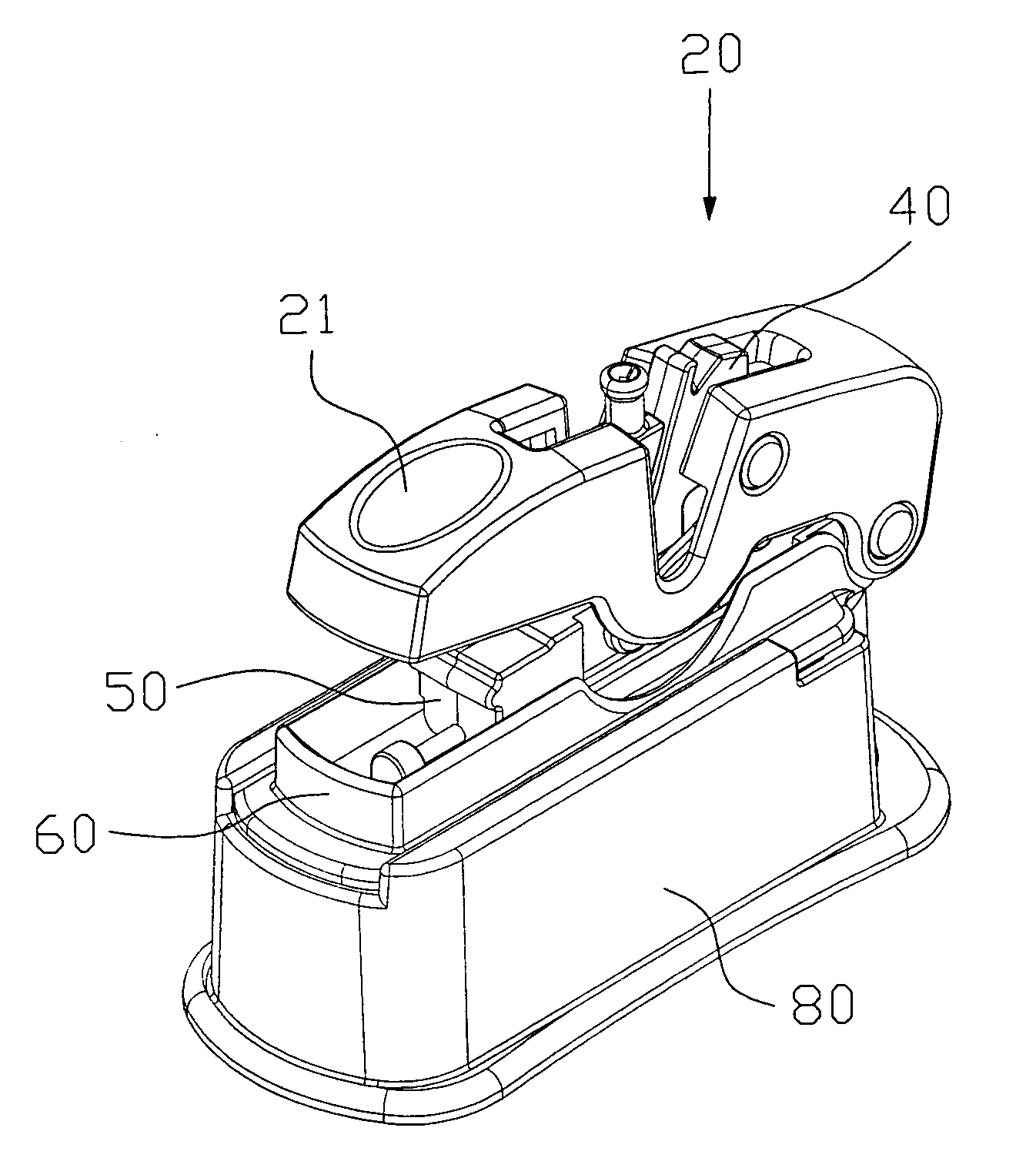
[0027]Referring to FIGS. 2˜4, the threader 20 of the present invention comprises: an upper holder block 21, a brake 30, a needle stand 40, a propeller 50, a base 60 and a detachable pedestal 80; an orifice 22 is arranged at central section of the upper holder block 21, and two holes 23, 24 at rear-end of both sides; a snapper 31 is arranged at central section on both sides of the brake 30, and a hole 32 on the front section; the needle stand 40 is provided with an adapting hole 41, a wiring duct 42, a notch 43, a blade hole 44, a threading groove 45, a V-shaped groove 47, a trough 46, a limitation slot 48 and a through-hole 49; of which, the blade hole 44 is provided with an embedded blade 73, and the trough 46 with a clamping s...


PUM


Abstract

The present invention provides a detachable threader, which permits an upper holder block to be connected separately with a brake and a base; and the brake is linked with a propeller; a threading sheet is fixed on the propeller; with the orientation pin and restoring spring on the base, the upper holder block can be controlled in a manner to make the threading sheet move freely in the threading groove of the needle stand; additionally, a V-shaped groove is arranged at the bottom of the adapting hole; after the needle is inserted into the adapting hole, it can align automatically the needle hole with the threading groove; moreover, the base is linked with the detachable pedestal, wherein the inner space with an oblique surface is used to accommodate the needle and stitch.

Description

BACKGROUND OF INVENTION[0001](1) Field of the Invention[0002]The present invention relates generally to a detachable threader, and more particularly to an innovative one which permits rapid threading into the needle hole by a push-type threading mechanism, and also provides a space for collecting the needle and thread.[0003](2) Description of the Prior Art[0004]Referring to FIG. 1, a conventional threading device 10 has a wider handheld portion 11, at front end of which there is a rhombic flexible steel wire 12. The flexible steel wire 12 is used for threading into the needle hole 14 of the needle 13 and also for threading of the stitch after passing through the needle hole 14.[0005]With this device, the users can align the flexible steel wire 12 of the threading device 10 with the needle hole 14 of the needle 13 and then pass through it, then, let the stitch thread the flexible steel wire 12; take out the flexible steel wire 12 from the needle hole 14, then the stitch is threaded i...

Claims


Application Information

Patent Timeline
IPC IPC(8): D05B87/00
CPCD05B87/02
Inventor CHANG, PI-CHAO
Owner CHANG PI CHAO
Learn More