Clamping arrangement and ejector and conical ring for the same
- Summary
- Abstract
- Description
- Claims
- Application Information
AI Technical Summary
Benefits of technology
Problems solved by technology
Method used
Image
Examples
Embodiment Construction
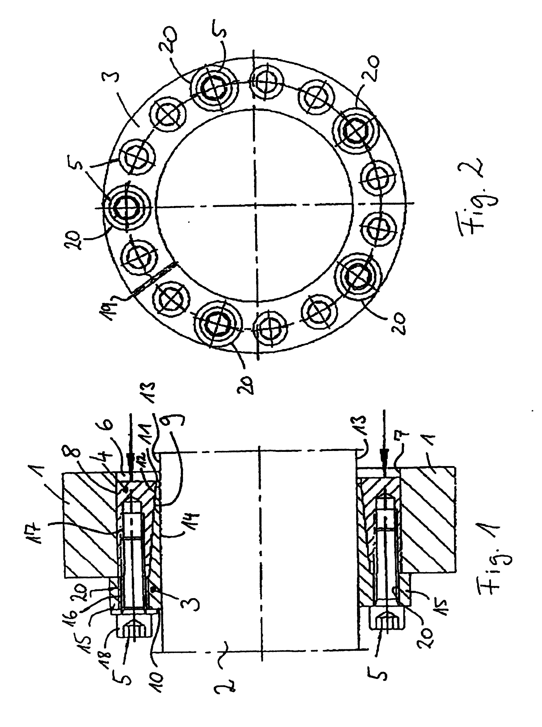
[0037]Referring now to the drawings wherein the showings are for the purpose of illustrating preferred and alternative embodiments of the invention only and not for the purpose of limiting same, FIGS. 1 and 2 shows a clamping arrangement to obtain a force-fit connection between a hub 1 and a shaft 2. More particularly, shown are an inner and an outer conical ring 3, 4 a that are braced by means of clamping screws 5 against one another, and against the hub 1 and the shaft 2.
[0038]For this purpose, the hub 1 has a recess 6, into which the shaft 2 with attached conical rings 3, 4 is inserted. The recess 6 forms a cylindrical surface 7 that faces the shaft2, and is designed here advantageously in the shape of a circular cylinder. The cylindrical surface 7 can also be designed to be conical, or in another advantageous way.
[0039]A peripheral surface 8, here also circular cylindrical, of the outer conical ring 4 comes in contact with the cylindrical surface 7. A conical peripheral surface ...
PUM
 Abstract
Description
Claims
Application Information
 - R&D
- Intellectual Property
- Life Sciences
- Materials
- Tech Scout
- Unparalleled Data Quality
- Higher Quality Content
- 60% Fewer Hallucinations
Browse by: Latest US Patents, China's latest patents, Technical Efficacy Thesaurus, Application Domain, Technology Topic, Popular Technical Reports.
© 2025 PatSnap. All rights reserved.Legal|Privacy policy|Modern Slavery Act Transparency Statement|Sitemap|About US| Contact US: help@patsnap.com


