
Tool Module for Heavy Equipment

a technology for heavy equipment and tools, applied in the field of construction vehicles, can solve the problems of high cost and high cost of heavy equipment vehicles, and achieve the effect of increasing control and safety of these operations

Inactive Publication Date: 2016-12-22
LANCE KEGAN J
View PDF8 Cites 0 Cited by
  • Summary
  • Abstract
  • Description
  • Claims
  • Application Information

AI Technical Summary

Benefits of technology

The patent describes a tool module that can be attached to heavy construction machines. This module contains a hydraulic winch or other hydraulic tool that can be controlled by the machine's operator. The module allows for increased control and safety when lifting and placing materials. The modular design of the tool allows for easy adaptability, as it can be mounted on different carrier vehicles and used with various alternative tools like a pole lifter or tree cutter.

Problems solved by technology

However, heavy equipment vehicles are particularly expensive, even cost prohibitive when considering some of the specialized functionality of certain vehicles.
However, each vehicle brand has its own proprietary mounting mechanisms and usually only make a limited number of, usually similar, tool attachments for their vehicles.

Method used


Image

  • Tool Module for Heavy Equipment
  • Tool Module for Heavy Equipment
  • Tool Module for Heavy Equipment

Examples


Embodiment Construction

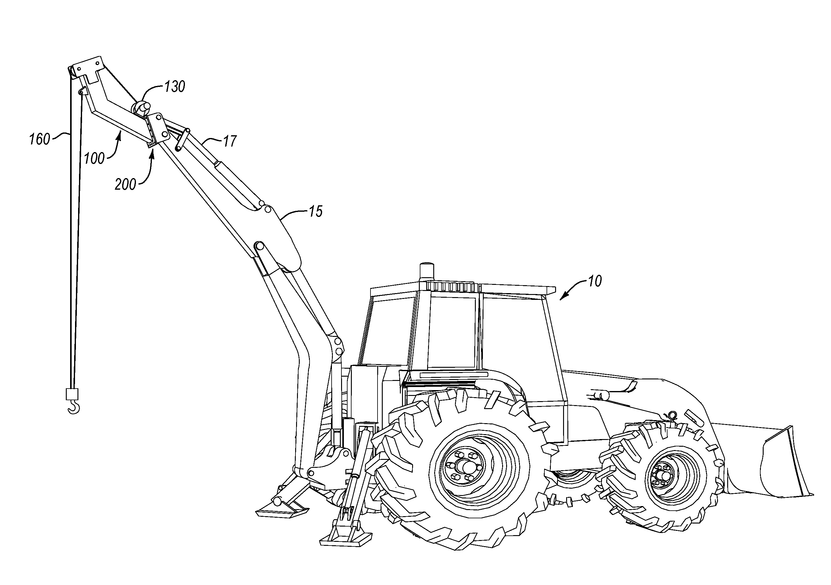
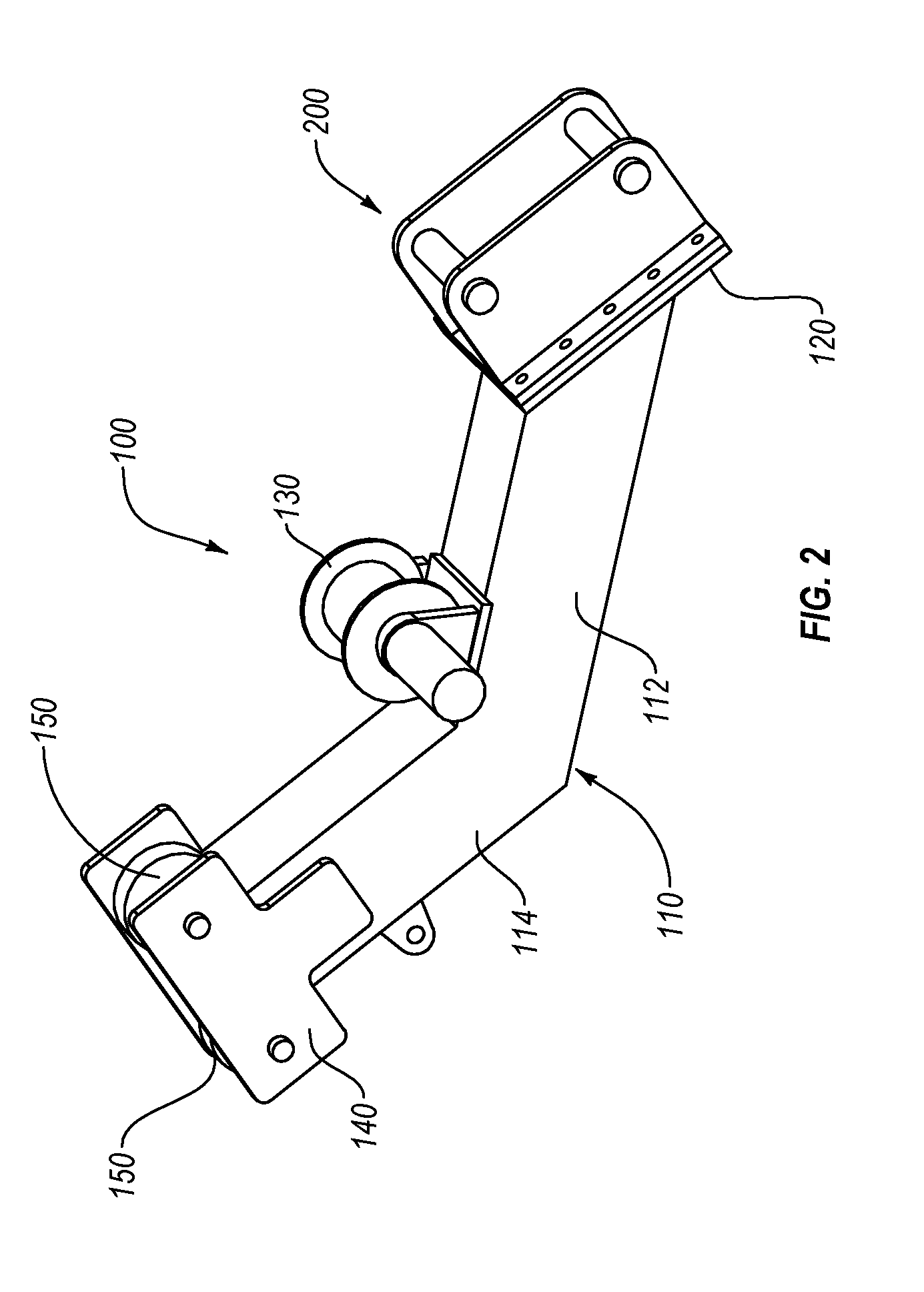
[0024]With reference now to the drawings, the preferred embodiment of the modular tool is herein described. It should be noted that the articles “a”, “an”, and “the”, as used in this specification, include plural referents unless the content clearly dictates otherwise. It should be noted that the preferred embodiment is depicted to be a winch or crane modular attachment; however, other tools may be incorporated other than a winch. These tools may be added to the basic winch embodiment disclosed, or may be separate embodiments, or may even be modular tool attachments, replacing the depicted winch. Limitations to only the winch embodiment, or even the tool options discussed herein, should not be inferred.

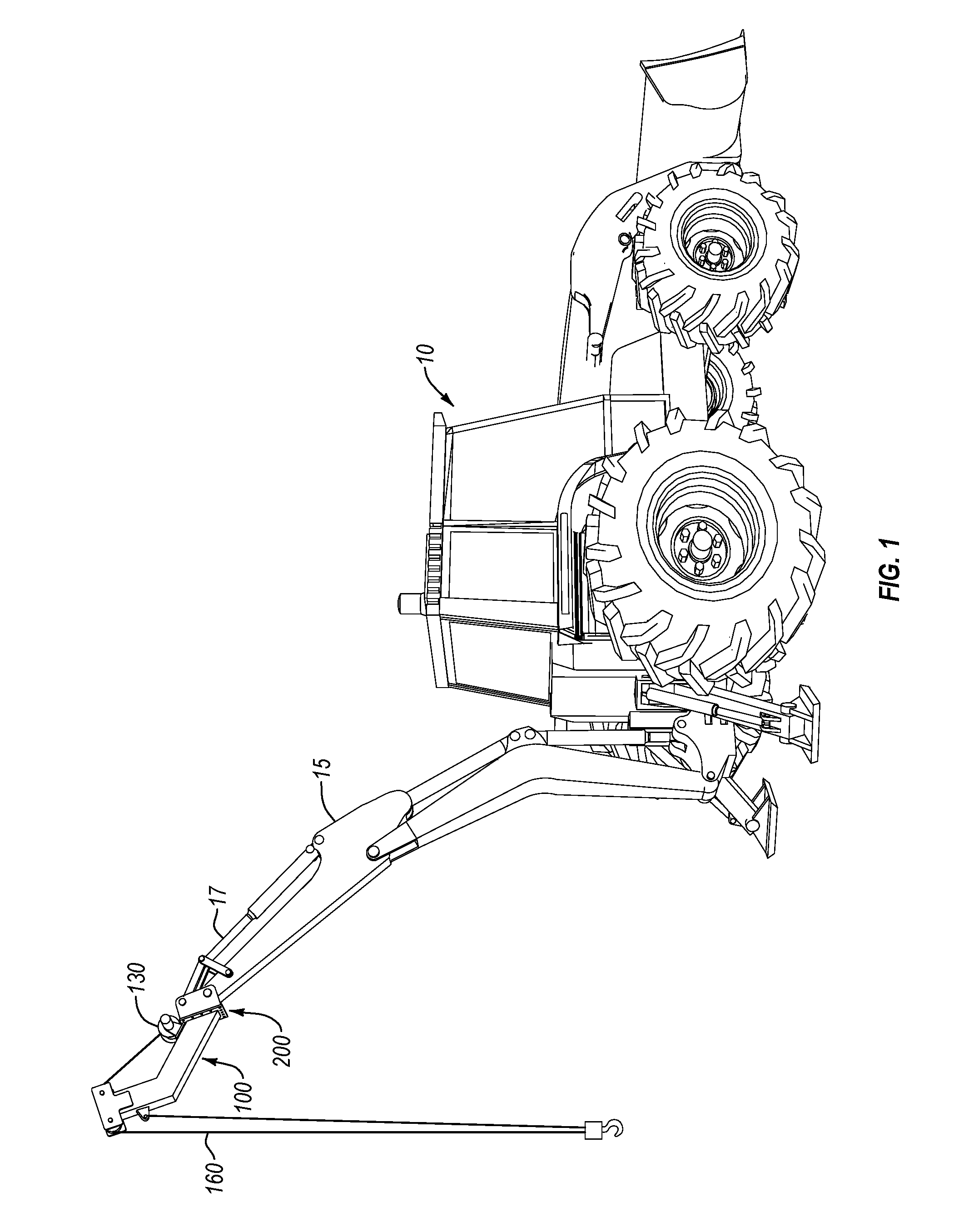
[0025]With reference to FIG. 1, a carrier vehicle, such as backhoe 10, has its primary tool replaced by a modular tool attachment, such as the winch attachment 100, depicted in FIG. 1. The backhoe 10 has the modular tool attachment 100 (in this case, a winch) mounted on its boom 15 an...


PUM


Abstract

A self-contained, fully functional modular crane attachment is meant for use on any piece of carrier equipment with hydraulics capable of operating it in place of a bucket attachment mechanism to turn carrier into a crane. The attachment is comprised of a main frame that runs parallel with the ground before angling upward. At the start of the attachment is a universal bolt plate meant to except any form of quick coupler plate or pin attachment so as to attach the attachment to any appropriate carrier machine. On top of the frame sits the hydraulic tool, which may be a winch, pole lifter, tree cutter, or other such tool. Finally, on the end of the frame furthest from the mounting plate may be a series of head pulleys that may direct a cable into the vertical axis for lifting.

Description

CROSS-REFERENCES TO RELATED APPLICATIONS[0001]This Application claims priority under 35 USC 119(e)(3) as a non-provisional perfection of prior filed U.S. Application No. 61 / 230,838, filed Thursday, Jun. 18, 2015, and incorporates the same by reference herein in its entirety.FIELD OF THE INVENTION[0002]The present invention relates to the field of construction vehicles and more particularly relates to a modular attachment for such vehicles to add additional tool functionality to the vehicle.BACKGROUND OF THE INVENTION[0003]Large construction vehicles are usually made with a specific purpose in mind. Accordingly, each vehicle has one or two tools with which it is made to accomplish its intended purpose. However, heavy equipment vehicles are particularly expensive, even cost prohibitive when considering some of the specialized functionality of certain vehicles. Each vehicle usually has a means of mounting and dismounting the tool. However, each vehicle brand has its own proprietary mou...

Claims


Application Information

Patent Timeline
IPC IPC(8): E02F3/96B66C23/36
CPCE02F3/964B66C23/36E02F3/963B66C23/44E02F3/3604
Inventor LANCE, KEGAN J.
Owner LANCE KEGAN J
Learn More