Screw machine

a screw machine and screw head technology, applied in the direction of cocoa, filtration separation, mixing/kneading with aerating apparatus, etc., can solve the problems of destroying the desired effect of venting, and difficult feeding of powdery bulk material into the extruder, etc., to achieve the effect of eliminating the clogging of the gas-permeable wall portion

Active Publication Date: 2010-08-12
COPERION
View PDF13 Cites 27 Cited by
  • Summary
  • Abstract
  • Description
  • Claims
  • Application Information

AI Technical Summary

Benefits of technology

[0007]The invention is based on the object of improving a possibility for eliminating a clogging of the gas-permeable wall portion.
[0010]As the metal nonwoven is itself not load-bearing, the measures, in which the metal nonwoven is supported by means of a gas-permeable support body with respect to the base body, in which the support body is formed as a support woven fabric, in which a gas-permeable drainage body is arranged between the support body and the base body, in which the drainage body is formed as a drainage woven fabric, in which the support woven fabric has a mesh width in the range of 100 μm to 400 μm and in which the drainage woven fabric has a mesh width in the range of 500 μm to 1000 μm, are of great advantage alternatively or cumulatively.
[0011]Screw machines, in which the base body has at least one partially cylindrical support face adapted to the inner wall of the at least one bore, against which support face the metal nonwoven is supported and in that holding strips are releasably attached to the base body and hold the metal non-woven in a clamping manner on the base body, in which the holding strips have clamping webs, which hold the metal nonwoven in a clamping manner against the base body, in which the base body is provided with edge webs surrounding the at least one support face, between which edge webs at least one of the support body and the drainage body are arranged, in which the holding strips are arranged flush with the inner wall of the at least one bore, in which the metal nonwoven is partially held in a clamping manner between the base body and at least one holding strip and in which the holding strips are formed as a holding frame, reflect, again alternatively or cumulatively, an advantageous configuration of the vacuum housing insert according to the invention, which allows a simple exchange of the metal nonwoven.

Problems solved by technology

It has been shown that, in the latter case, the wall of the porous wall portion facing the bore was clogged by partially plasticized plastics material and therefore the desired effect of venting was destroyed.
There, the basic problem is assumed that feeding powdery bulk material into an extruder is difficult.
It is disadvantageous that apart from gas, part of the powdery solid material is also drawn off through the openings.
Thus, adequate operating reliability and economy are not ensured.
Moreover, the risk also exists of clogging the filter openings by the powdery bulk material.
In the extreme case, the gas-permeable wall portion becomes unusable owing to clogging of the pores or microchannels, with it also not being possible to eliminate this effect by a back-flush.
There is a high outlay in terms of work and cost for exchanging or repairing a wall portion of this type consisting of sintered metal and being gas-permeable per se.
One of the reasons for the clogging is that the filter fineness of sintered metals of this type is not small enough, so bulk material particles penetrate into the sintered metal and clog it.

Method used


Image

  • Screw machine
  • Screw machine
  • Screw machine

Examples


Embodiment Construction

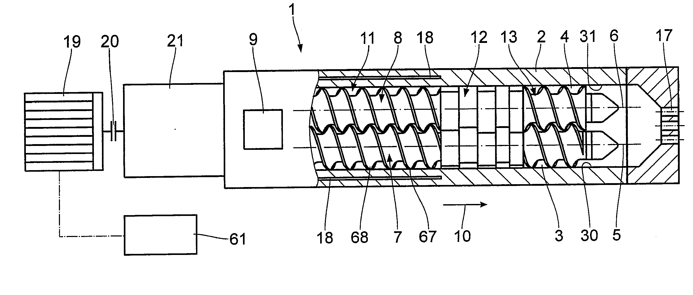
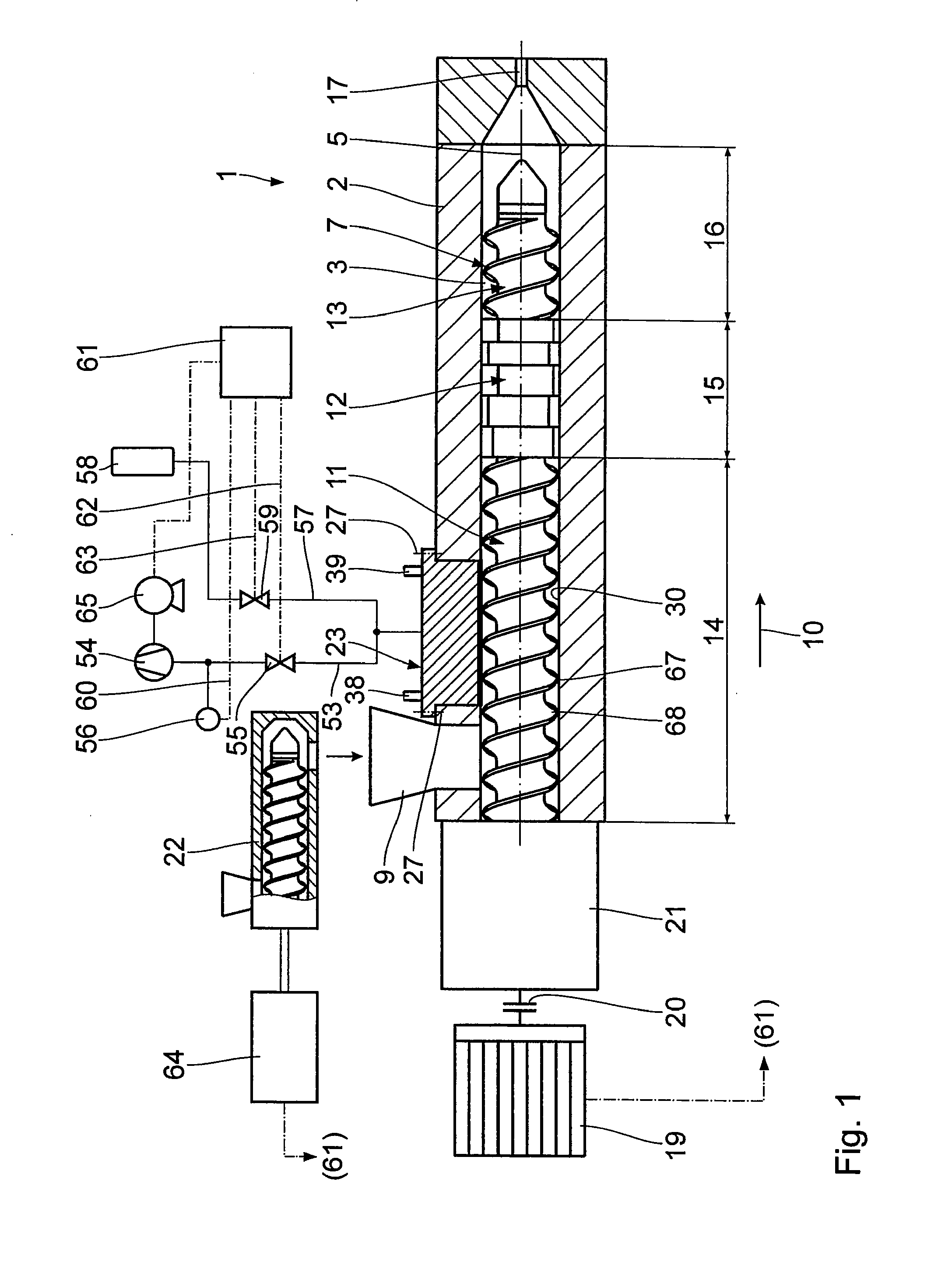
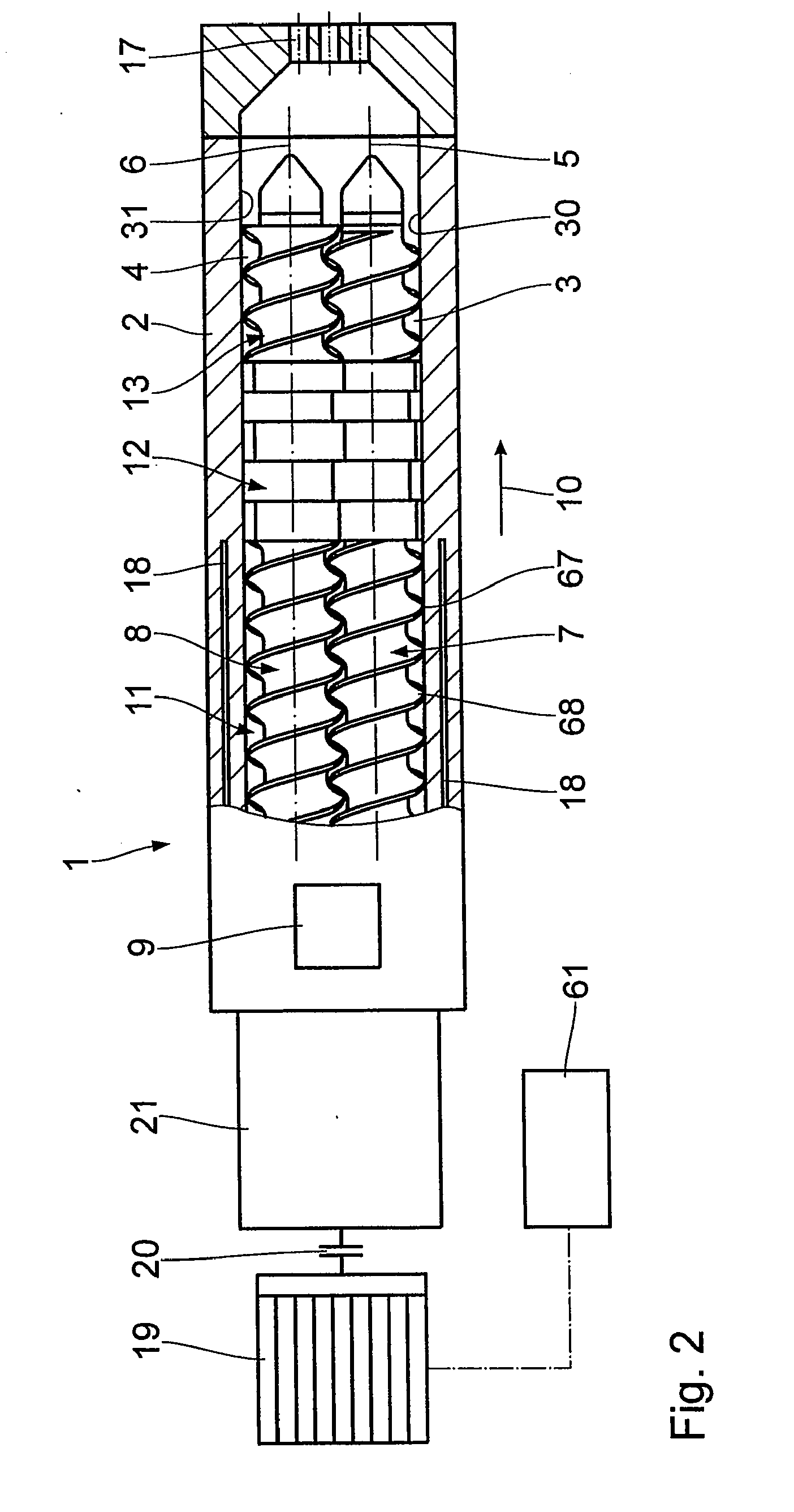
[0022]The extruder system shown in FIGS. 1 and 2 has a screw machine formed as an extruder 1. Figure of eight-shaped interconnected housing bores 3, 4, the axes 5, 6 of which extend parallel to one another, are formed in the housing 2 thereof generally consisting of a plurality of housing sections. Arranged in the housing bores 3, 4 are two screws 7, 8. The screws are formed as closely meshing screws 7, 8 rotating in the same direction. A feed funnel 9 opens into the bores 3, 4 at one end, which is on the left in FIGS. 1 and 2. Proceeding from the feed funnel 9, provided in the conveying direction 10 are the screws 7, 8 with a first conveying screw portion 11, adjoining this a kneading disc portion 12 and again a second conveying screw portion 13.

[0023]The first conveying screw portion 11 extends over an intake zone 14 acting as a solid material conveying zone. The kneading disc portion 12 defines a melting zone 15 here. The seconding conveying screw portion 13 defines a pressure bu...


PUM

PropertyMeasurementUnit
Lengthaaaaaaaaaa
Lengthaaaaaaaaaa
Widthaaaaaaaaaa

Abstract

A screw machine for treating at least partially powdery bulk material has a housing with at least one housing bore and a screw arranged in the housing bore. A vacuum housing portion is provided, which is formed as a vacuum housing insert, which is releasably attached in the housing, in which a metal nonwoven is exchangeably held as a gas-permeable wall portion on a base body.

Description

FIELD OF THE INVENTION[0001]The invention relates to a screw machine for treating at least partially powdery bulk material, with a housing, which has at least one housing bore with an inner wall, with a feed opening for the bulk material arranged at one end of the housing, with a respective screw arranged in the at least one housing bore, with a metering device arranged upstream of the feed opening for feeding the bulk material, with a vacuum housing portion in the intake zone, which has a gas-permeable wall portion delimiting the at least one housing bore, and with a drive for the at least one screw.BACKGROUND OF THE INVENTION[0002]A screw machine of this type formed as an extruder is known from DE 1 729 395 B (corresponding to GB 1 277 150). A normal sieve or a filter made of sintered material is provided there as a vacuum housing portion in order to bring about a venting of the bulk material to be processed containing a large amount of air. The porous wall portion may be level an...

Claims


Application Information

Patent Timeline
IPC IPC(8): B01F13/06B01D53/22B29C48/50B29C48/38B29C48/76
CPCB01D39/2041B29C47/369B01D2239/065B01D2239/0654B01D2239/1216B29C47/0009B29C47/0016B29C47/0801B29C47/10B29C47/38B29C47/402B29C47/763B29C47/767B29C47/82B29C47/825B29C2791/006B29C2947/92514B29C2947/92657B29C2947/92828B29C2947/92895B29C47/1027B29C47/6056B01D2239/0613B29C48/83B29C48/288B29C48/03B29C48/06B29C48/252B29C48/285B29C48/39B29C48/395B29C48/402B29C48/57B29C48/763B29C48/767B29C48/797B29C48/834B29C2948/92514B29C2948/92657B29C2948/92828B29C2948/92895B29B7/483B29B7/488B29B7/845B29B7/86B29C48/40
Inventor STIRNER, THORSTEN
Owner COPERION
Why Eureka
Try Eureka