Sailing ship equipped with a hard sail

a technology for sailing ships and sails, applied in the direction of marine propulsion, special-purpose vessels, vessel construction, etc., can solve problems such as obstructing the passage of ships under bridges

Inactive Publication Date: 2010-08-12
OUCHI OCEAN CONSULTANT +1
View PDF2 Cites 5 Cited by
  • Summary
  • Abstract
  • Description
  • Claims
  • Application Information

AI Technical Summary

Benefits of technology

[0005]In accordance with the present invention, there is provided a sailing ship equipped with a hard sail comprising a hard sail assembly comprising a plurality of hard sails of wing-shaped hollow cross section vertically stacked so that each except the lowermost is received in the one immediately below, first means for driving the hard sails to move each except the lowermost toward and away from the one immediately below, a post extending vertically to support the lowermost hard sail, and second means for rotating the post around its longitudinal axis, wherein overlapping lengths between vertically adjacent hard sails are variably controlled to make the hard sail assembly expand and contract vertically.
[0008]In accordance with a preferred embodiment of the present invention, each hard sail is provided with members for maintaining the wing-shaped hollow cross section at the lower end and near the upper end. The member near the upper end is a frame surrounding the outer circumferential surface of the hard sail. The frame abuts the upper end of the hard sail immediately below to prevent the downward movement of the hard sail relative to the hard sail immediately below.
[0009]It is desirable to provide each hard sail with members for maintaining the wing-shaped hollow cross section at the lower end and near the upper end. The member near the upper end is desirably a frame surrounding the outer circumferential surface of the hard sail to abut the upper end of the hard sail immediately below when the hard sail assembly contracts, thereby preventing the downward movement of the hard sail relative to the hard sail immediately below. Thus, the contracted hard sail assembly becomes stable.
[0011]When swing arms engage the members for maintaining the wing-shaped hollow cross section provided at the lower ends of the hard sails vertically adjacent to each other, and the third means drives the swing arms to make them swing, the upper hard sails move toward and away from the hard sails immediately below. Thus, overlapping lengths between vertically adjacent hard sails can be variably controlled.

Problems solved by technology

Therefore, the hard sail may obstruct passage of the ship under bridges.

Method used


Image

  • Sailing ship equipped with a hard sail
  • Sailing ship equipped with a hard sail
  • Sailing ship equipped with a hard sail

Examples


Embodiment Construction

[0015]Preferred embodiments of the present invention will be described.

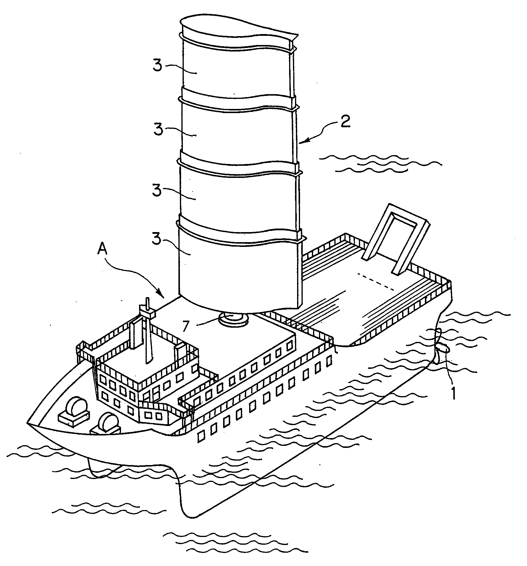
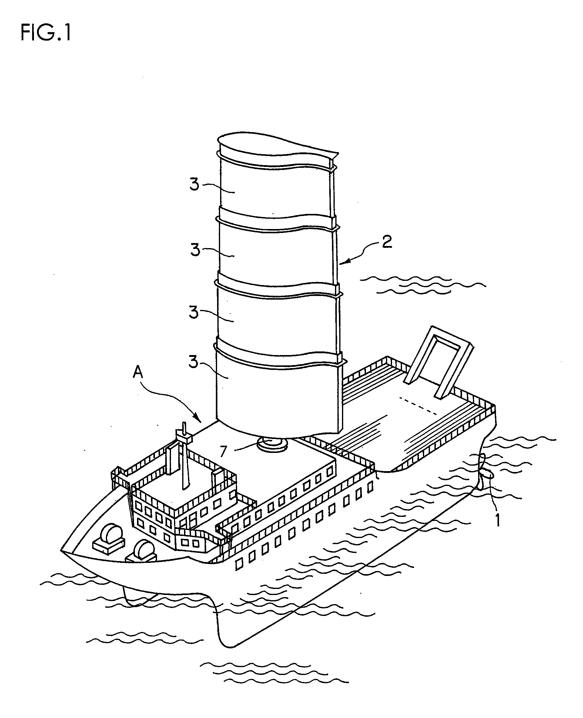
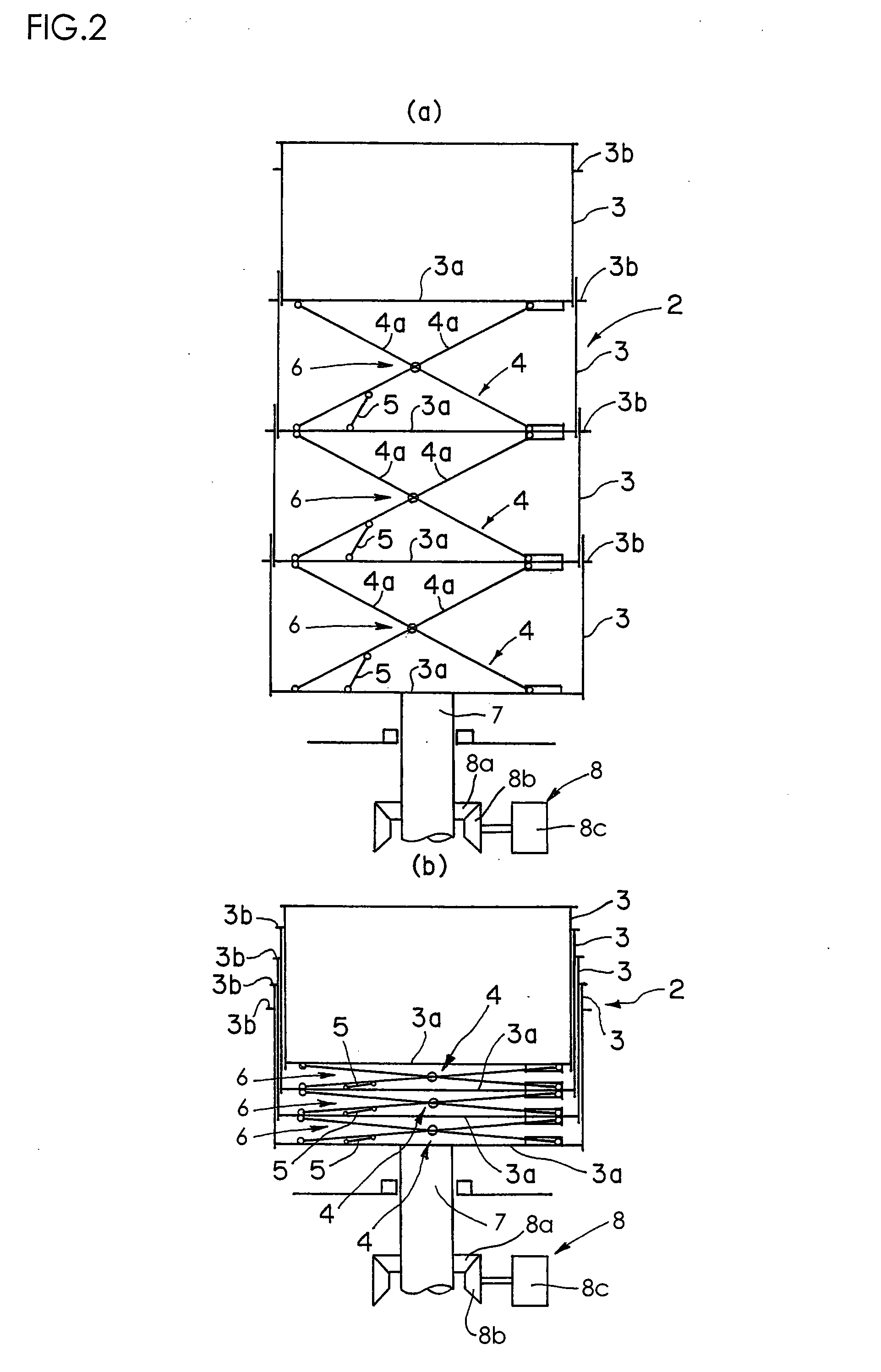
[0016]As shown in FIG. 1, a catamaran type ocean research ship A is equipped with a propeller propulsion unit 1 and further with a wind-force propulsion unit of hard sail assembly 2. The hard sail assembly 2 is, as shown in FIGS. 1 and 2, provided with four hard sails 3 made of carbon fiber reinforced plastic. The four hard sails 3 are vertically stacked. Each of the hard sails 3 has a symmetrical wing-shaped hollow cross section. Each of the upper three hard sails 3 is telescopically received in the hard sail 3 immediately below. Each hard sail 3 is provided with a bottom plate 3a and with a frame 3b surrounding the outer circumferential surface of a region near the upper end of the hard sail 3.

[0017]A pantograph 4 is provided between each pair of vertically adjacent hard sails 3 to engage the bottom plate 3a of the upper hard sail 3 and the bottom plate 3a of the lower hard sail 3 through articulated couplings....


PUM


Abstract

A sailing ship comprises a hard sail assembly. The hard sail assembly comprises a plurality of hard sails of wing-shaped hollow cross section. The hard sails are vertically stacked so that each except the lowermost is received in the one immediately below. The sailing ship further comprises means for driving the hard sails to move each except the lowermost toward and away from the one immediately below, a post extending vertically to support the lowermost hard sail, and second means for rotating the post around its longitudinal axis. Overlapping lengths between vertically adjacent hard sails are variably controlled to make the hard sail assembly expand and contract vertically.

Description

BACKGROUND OF THE INVENTION[0001]The present invention relates to a sailing ship equipped with a hard sail.[0002]A sailing ship equipped with a hard sail is disclosed in Japanese Patent Laid-Open Publication No. 2005-280533.[0003]The hard sail can be contracted transversely but its height cannot be changed. Therefore, the hard sail may obstruct passage of the ship under bridges.SUMMARY OF THE INVENTION[0004]An object of the present invention is to provide a sailing ship equipped with a hard sail of changeable height.[0005]In accordance with the present invention, there is provided a sailing ship equipped with a hard sail comprising a hard sail assembly comprising a plurality of hard sails of wing-shaped hollow cross section vertically stacked so that each except the lowermost is received in the one immediately below, first means for driving the hard sails to move each except the lowermost toward and away from the one immediately below, a post extending vertically to support the lowe...

Claims


Application Information

Patent Timeline
Patent Type & Authority Applications(United States)
IPC IPC(8): B63H9/06
CPCB63H9/0607B63B15/0083B63B2015/0041B63H9/1021B63H9/061
Inventor OUCHI, KAZUYUKIKIMURA, GAKU
Owner OUCHI OCEAN CONSULTANT
Why Eureka
Try Eureka