
String intrument

Inactive Publication Date: 2010-08-12
KAMENSKY JODY M
View PDF2 Cites 9 Cited by
  • Summary
  • Abstract
  • Description
  • Claims
  • Application Information

AI Technical Summary

Problems solved by technology

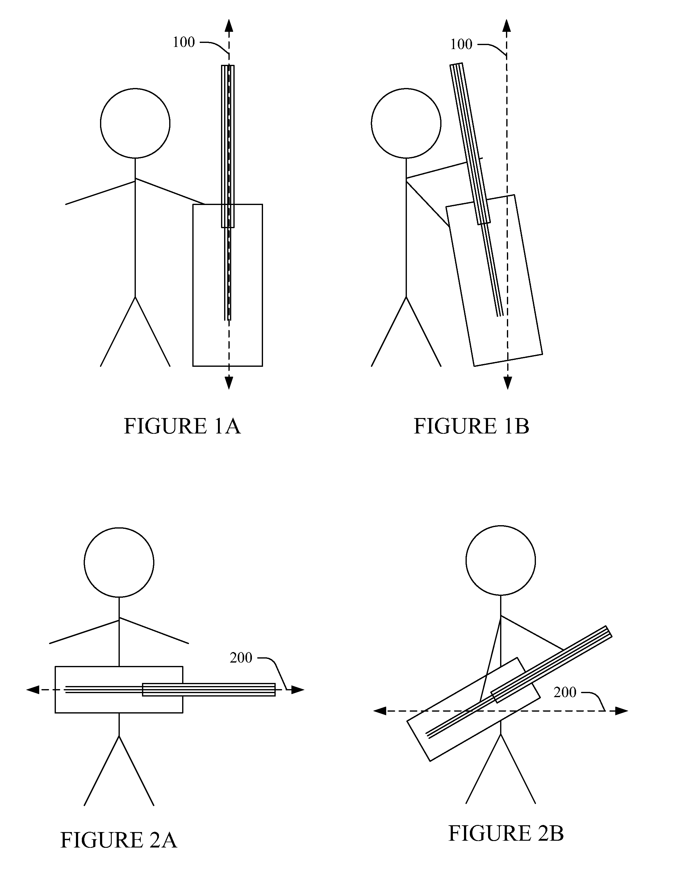
Unfortunately, the above-note physical layout of the neck with respect to the body tends to cause the user of the string instrument to re-position the string instrument off a generally vertical or horizontal axis with respect to the ground to position the neck for playing the instrument.

Method used


Image

  • String intrument
  • String intrument
  • String intrument

Examples


Embodiment Construction

[0013]The following generally relates to string instruments such as a guitar, violin, cello, viola, bass, mandolin, banjo, harp, and / or other string instruments. However, for brevity and clarity, the following is described in connection with a guitar.

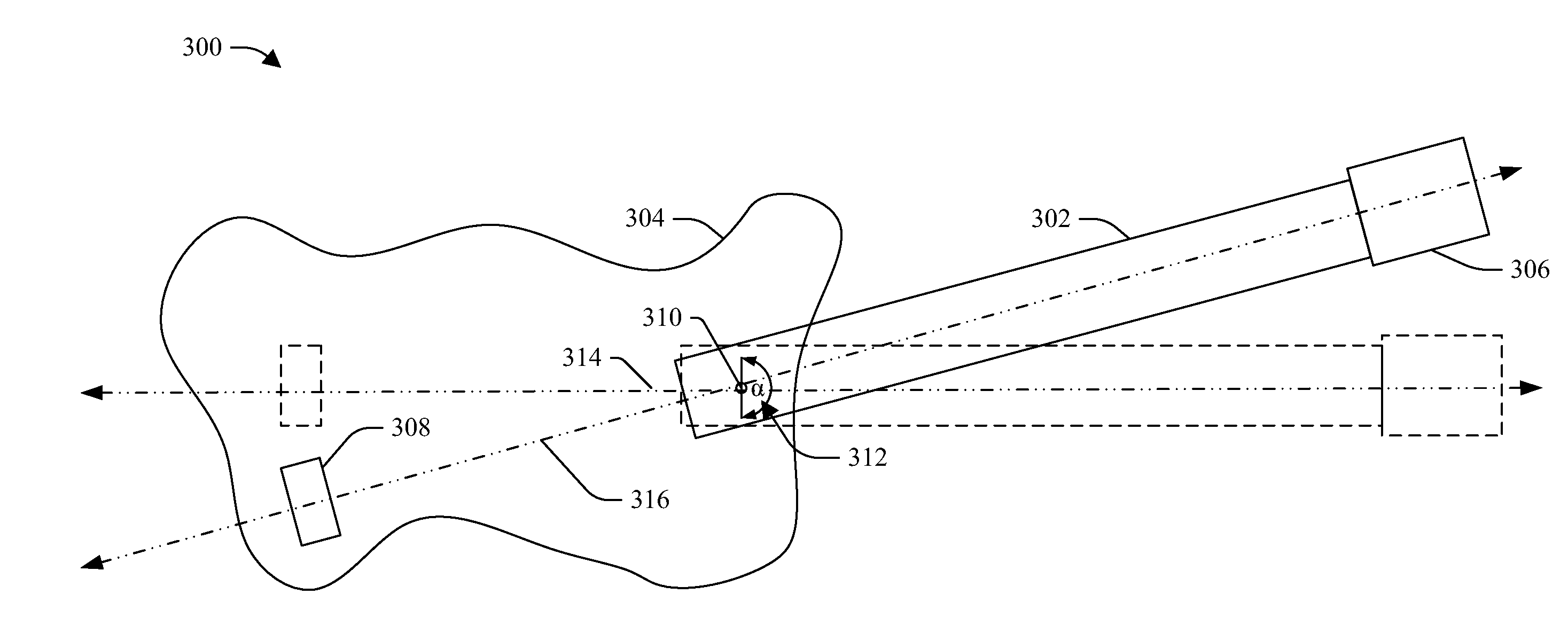
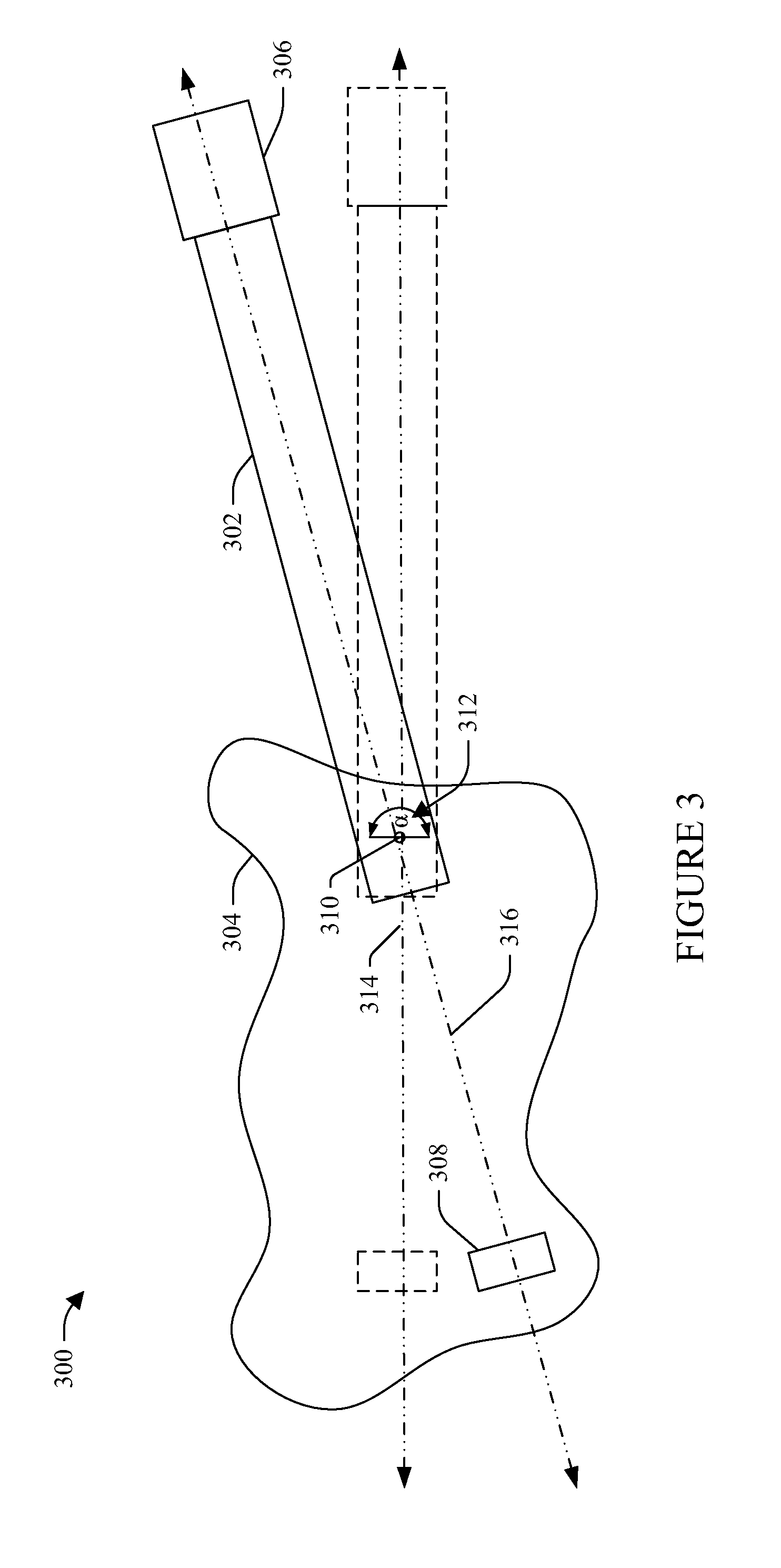
[0014]Initially referring to FIG. 3, an example string instrument 300 is illustrated. The string instrument includes a neck 302 and a body 304. The illustrated body 304 has an irregular shape. In other embodiments, the body 304 is otherwise shaped. A headstock 306 is affixed to the neck 302, and a bridge 308 is attached to the body 304. When strings are installed on the string instrument 300, they extend between the headstock 306 and the bridge 308, along the neck 302.

[0015]The neck 302 is attached to body 304 via a fastener 310 such as a screw, a bolt, or the like. The fastener 310 secures the neck 302 at a fixed location. The fastener 310 can also be loosened (or removed) to allow the neck 302 to pivot about the fastener 310 (or a piv...


PUM


Abstract

A string instrument includes a body portion having a first longitudinal axis, an elongate neck portion having a second longitudinal axis and first and second opposing ends located along the second longitudinal axis, and a fastener that secures one of the first or second ends to the body portion, wherein the first and second axes are misaligned from each other in a same plane.

Description

CROSS REFERENCE TO RELATED APPLICATIONS[0001]This application claims the benefit of priority of provisional patent application Ser. No. 61 / 207,295, filed on Feb. 10, 2009, and entitled “ANSIR,” which is incorporated herein in its entirety by reference.TECHNICAL FIELD[0002]The following generally relates to string instruments.BACKGROUND[0003]A string instrument generally includes a body portion having longitudinal axis and an elongate neck portion having first and second opposing ends. One of the ends of the neck is attached to the body via a joint such as a glue or bolt, and the neck extends along the longitudinal axis. A headstock is attached to the other end of the neck. A fretboard is attached to the neck, and a plurality of frets are affixed to the fretboard. A bridge is attached to the body along the longitudinal axis. A set of strings are strung along the longitudinal axis and hence the neck between the headstock and the bridge.[0004]Unfortunately, the above-note physical layo...

Claims


Application Information

Patent Timeline
IPC IPC(8): G10D3/00G10D1/08G10D1/02G10D1/04G10D1/10G10D1/00G10D3/06
CPCG10D3/06G10D1/00
Inventor KAMENSKY, JODY M.
Owner KAMENSKY JODY M
Learn More