
Housing-Piston Assembly for a Coupling Device and Assembly Method

a technology of coupling device and housing piston, which is applied in the direction of automatic clutches, gearing, forging/pressing/hammering apparatuses, etc., can solve the problem of weakening the strength of the structur

Active Publication Date: 2010-08-05
ZF FRIEDRICHSHAFEN AG
View PDF4 Cites 4 Cited by
  • Summary
  • Abstract
  • Description
  • Claims
  • Application Information

AI Technical Summary

Benefits of technology

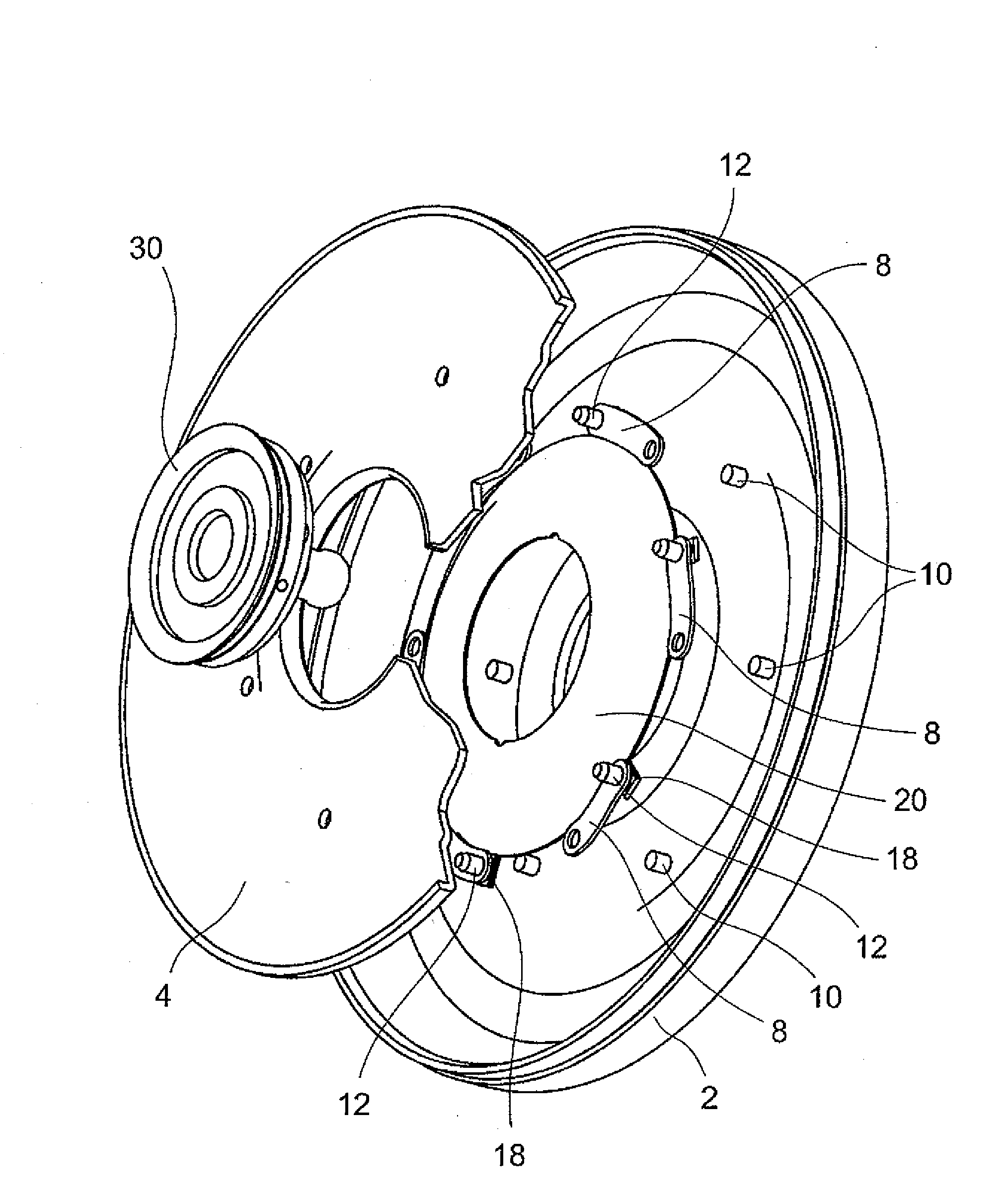
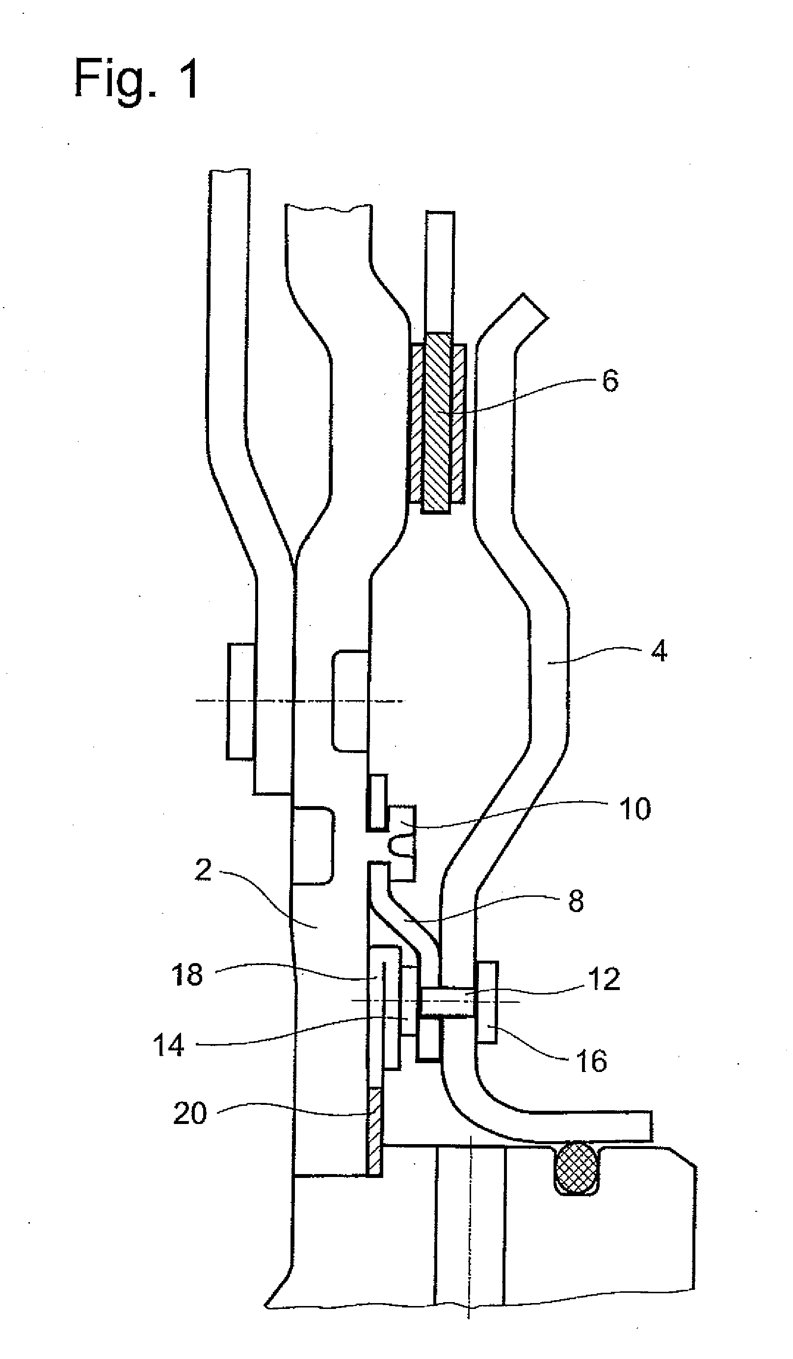
[0011]As a result of the introduction and use of a support element, which is introduced in each case between the components which have already been connected to each other in a first step, i.e., which have been riveted together or which have been formed as integral parts of each other, this support element also comprising anvil sections which come to lie behind the set heads of the rivets yet to be set, the components now to be riveted in the second step can be riveted from the accessible front side without the need for access openings in the housing or in the piston. There is therefore no longer any need to provide corresponding holes or to plug them after the riveting. This simplifies production and assembly, both of which become less expensive, and any possible impairments to the strength and or leak-tightness of the assembly are avoided.
[0030]The inventive method has been described here as a method for assembling a housing-piston assembly. Nevertheless, a method of this type can also be used for other types of assembly jobs in which the conditions are similar to those present during the riveting of a housing-piston assembly, that is, especially in cases where several elements are to be riveted to each other, namely, elements which make it difficult to impossible to obtain direct access to the set heads of the individual rivets during one of the work procedures. The person of ordinary skill will easily see other possible applications, especially in the area of the assembly of motor vehicles, bicycles, etc. Accordingly, there will also be additional areas of application for the inventive support element or for an inventive auxiliary device.

Problems solved by technology

The possibility cannot be excluded, furthermore, that the strength of the structures might be impaired by the holes which must be provided or even that leaks can result.

Method used


Image

  • Housing-Piston Assembly for a Coupling Device and Assembly Method
  • Housing-Piston Assembly for a Coupling Device and Assembly Method
  • Housing-Piston Assembly for a Coupling Device and Assembly Method

Examples


Embodiment Construction

[0043]FIG. 1 shows a part of a housing-piston assembly, comprising a housing cover 2, which is part of a housing of a coupling device, such as a wet-running multi-plate clutch or a bridging clutch of a hydrodynamic coupling device; and a piston 4, which can be brought into engagement with a clutch plate 6 by movement in the axial direction, that is, in the direction toward or away from the housing cover 2 to push this plate against the housing cover 2 and thus to establish a nonpositive connection between the housing cover 2 and the clutch plate 6.

[0044]The piston 4 is connected to the housing cover 2 by connecting elements 8, which are designed as leaf springs, for example, where the connecting elements 8 are attached to the housing cover 2 by rivets 10. In the present example, the rivets 10 are formed directly on the housing cover 2. The piston 4 in turn is attached to the connecting elements 8 by rivets 12, the set heads 14 of which face the housing cover 2, whereas the closing h...


PUM

PropertyMeasurementUnit
freedom of movementaaaaaaaaaa
movementaaaaaaaaaa
areaaaaaaaaaaa

Abstract

A housing-piston assembly for a coupling device, especially a wet-running, multi-plate clutch or a bridging clutch of a hydrodynamic coupling device, wherein the piston (4) is attached to a housing (2) by means of connecting elements (8) in such a way that it has a certain freedom of movement, and rivets (10, 12) are provided as fastening elements between the piston (4) and the connecting elements (8) and / or between the connecting elements (8) and the housing (2), and wherein at least one support element (20, 36, 70, 86) can be positioned in a riveting position between the piston (4) and the connecting elements (8) and / or between the connecting elements (8) and the housing (2) in such a way that anvil sections (18, 44, 74, 92) of the support element (20, 36, 70, 86) lie behind the set heads (14) of their associated rivets (10, 12). A method of assembling a housing-piston assembly is also provided.

Description

RELATED APPLICATIONS[0001]This application claims priority from U.S. Provisional Patent Application Ser. No. 61 / 149,791 which was filed on Feb. 4, 2009 and claims priority of German Application No. 10 2009 000 959.0 which was filed on Feb. 18, 2009.BACKGROUND OF THE INVENTION[0002]1. Field of the Invention[0003]The invention pertains to a housing-piston assembly for a coupling device, especially a wet-running multi-plate clutch or a bridging clutch of a hydrodynamic coupling device, where the piston is attached to a housing by connecting elements in such a way that it has a certain freedom of movement and rivets are provided as fastening elements between the piston and the connecting elements and / or between the connecting elements and the housing, a support element for use in a housing-piston assembly of this type, an auxiliary device for riveting a housing-piston assembly of this type, and a method for assembling a housing-piston assembly of this type, in which, in a first step, th...

Claims


Application Information

Patent Timeline
Patent Type & Authority Applications(United States)
IPC IPC(8): F16D13/70F16H45/02F16D25/00B23P11/00B21J15/02
CPCB21J5/02B21J15/10B21J15/14B21J15/36B21K25/00Y10T29/5377F16D2048/0212F16H45/02Y10T29/49943Y10T29/49956F16D25/0635
Inventor ZUEHL, CARSTENSCORDINO, MIKEUMNUS, CLAUSCUPERKA, JURAJREINHARDT, BERNDHAMBLIN, RAYWALTER, OLIVERMUNCH, MATTHIAS
Owner ZF FRIEDRICHSHAFEN AG
Learn More