
Vehicle seat frame

a seat frame and seat back technology, applied in the direction of seat backs, pedestrian/occupant safety arrangements, safety belts, etc., can solve the problem of not being able to effectively ensure the strength of the seat back frame, and achieve the effect of preventing weight increase and effectively ensuring strength

Inactive Publication Date: 2010-07-29
AISIN SEIKI KK
View PDF13 Cites 15 Cited by
  • Summary
  • Abstract
  • Description
  • Claims
  • Application Information

AI Technical Summary

Benefits of technology

[0007]The present invention was made in consideration with the above problems and the object of the invention is to provide a vehicle seat frame which can prevent weight increase and effectively secure the strength.Means for Solving the Problem
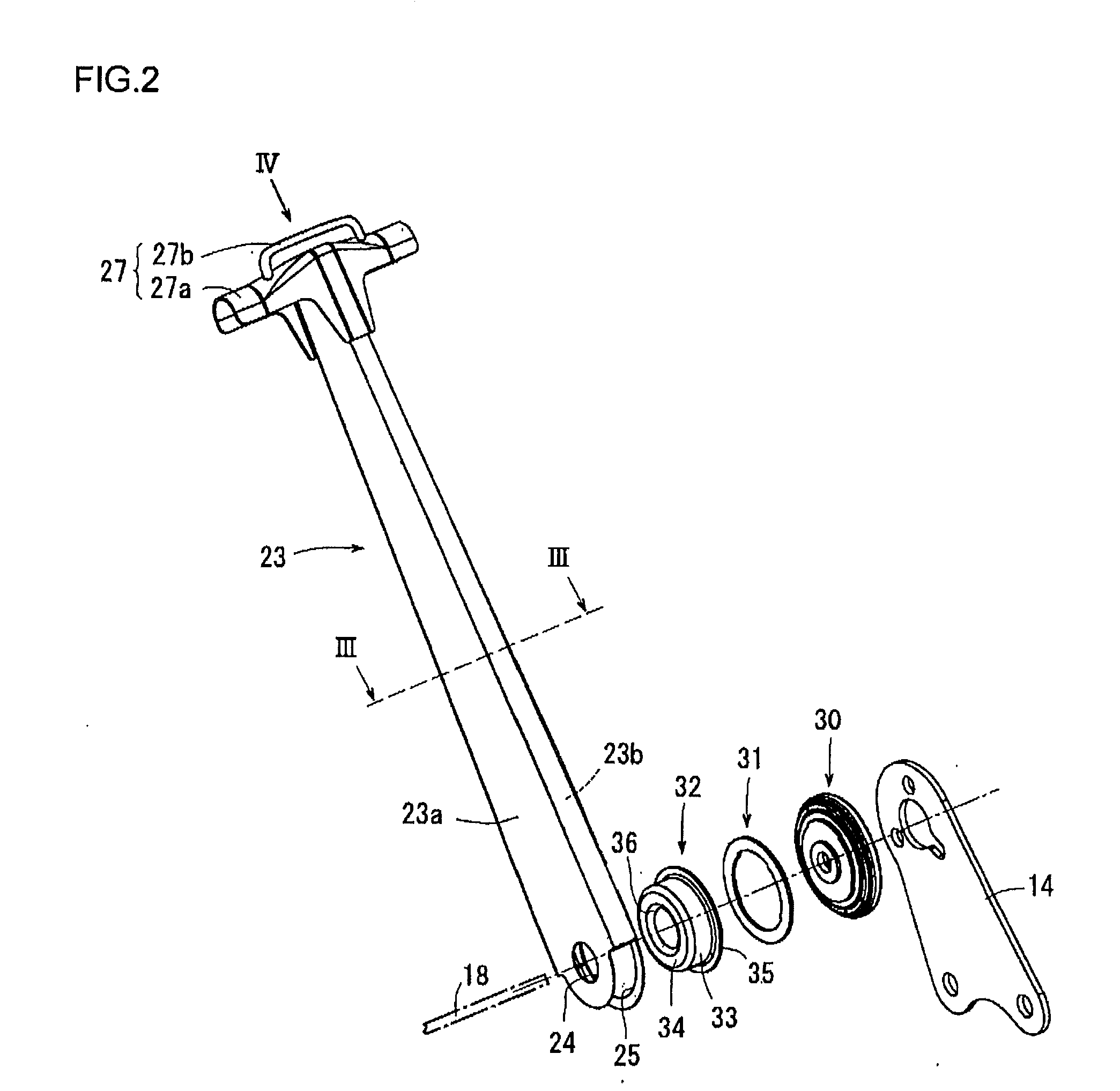
[0012]According to the vehicle seat frame in the first aspect, at least one of the seat cushion frame and the seat back frame has a hollow quadrangular prism shaped outer peripheral portion and a reinforcement plate accommodated in the outer peripheral portion. The reinforcement plate is provided in parallel with a direction of load to be applied on the shoulder belt anchor from the shoulder belt under an occupant of the vehicle being restrained thereby. When the seat belt is locked upon the vehicle being under sudden deceleration condition, a large load is applied on the back center frame of the seat back frame through the shoulder belt anchor. However, the reinforcement plate is provided in parallel with the direction of the load applied on the shoulder belt anchor through the shoulder belt and accordingly the deformation of the seat back frame can be sufficiently avoided even the reinforcement plate is made from a thin wall plate. Accordingly, the vehicle seat frame can prevent an increase of the weight and effectively ensure the strength.
[0013]According to the vehicle seat frame in the second aspect, the outer peripheral portion and the reinforcement plate are formed from a single steel plate by bending and connecting both ends of the bent steel plate. This can reduce the number of component.
[0014]According to the vehicle seat frame in the third aspect, the outer peripheral portion and the reinforcement plate are extending in a vehicle upward direction and the shoulder belt anchor is provided at an upper end thereof. Accordingly, the load applied on the shoulder belt anchor from the shoulder belt is mostly received at the outer peripheral portion and the reinforcement plate to restrain the deformation of the seat back frame.
[0015]According to the vehicle seat frame in the fourth aspect, the shoulder belt anchor includes a joint portion and a belt guide portion and the joint portion extends in a vehicle width direction and supports an outer side surface of the outer peripheral portion in a vehicle longitudinal direction. According to this structure, a load applied to the shoulder belt anchor from a shoulder belt is mostly received at the outer peripheral portion and the reinforcement plate. Further, the belt guide portion extends in the vehicle width direction apart from the joint portion with a predetermined distance and is connected to the joint portion at bent ends thereof. Therefore, the shoulder belt is easily inserted through the joint portion and the belt guide portion with a simple structure. Further, the reinforcement plate is arranged in parallel with a direction in which the shoulder belt inserted between the joint portion and the belt guide portion is extracted towards a buckle provided at a side portion of the seat cushion frame. Accordingly, the deformation of the seat back frame can be sufficiently prevented even a thin walled reinforcement plate is used.

Problems solved by technology

However, according to the above conventional vehicle seat frame disclosed in the Patent Document 1, the direction of load applied on the back center frame of the seat back frame from the seat belt through the shoulder belt anchor upon vehicle sudden deceleration, is not incorporated into the design and it would not be an effective solution to ensure the strength of the seat back frame.

Method used


Image

  • Vehicle seat frame
  • Vehicle seat frame
  • Vehicle seat frame

Examples


Embodiment Construction

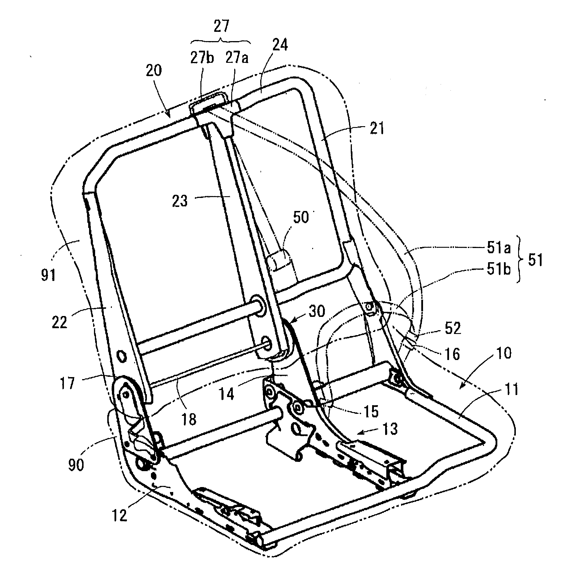
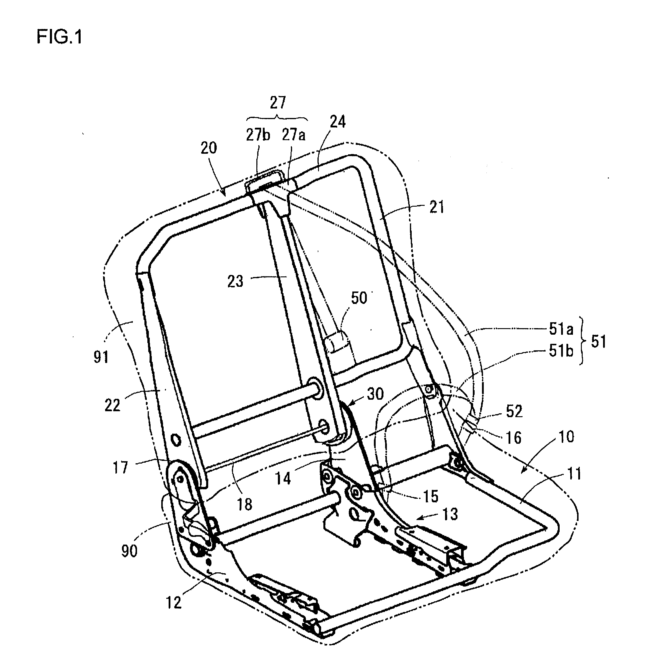
[0023]The vehicle seat frame according to the embodiment of the invention will be explained hereinafter with reference to the attached drawings. The vehicle seat frame of the embodiment, as shown in FIG. 1, includes a seat cushion frame 10 supporting a seat cushion 90, a seat back frame 20 supporting a seat back 91, a recliner 30 rotatably connecting the seat back 91 relative to the seat cushion and adjusting the relative rotation angle thereof and a shoulder belt anchor 27 provided at an upper portion of the seat back frame 20. The shoulder belt anchor 27 includes a joint portion 27a and a belt guide portion 27b.

[0024]Back side frames 21 and 22 are provided at both sides of the seat back frame 20, respectively and a hollow quadrangular prism shaped back center frame 23 is provided at the central portion of the seat back frame 20. Upper end portions of the back side frames 21 and 22 are connected together by an upper pipe 24 and the central portion of the upper pipe 24 is connected...


PUM


Abstract

A vehicle seat frame is provided, which can prevent the increase of weight and secure the strength effectively. The vehicle seat frame comprises a seat cushion frame supporting a seat cushion, a seat back frame supporting a seat back, a recliner rotatably connecting the seat back relative to the seat cushion and adjusting the rotation angle thereof and a shoulder belt anchor provided on the seat back frame for supporting one end of a shoulder belt. The back center frame of the seat back frame includes a hollow quadrangular shape outer peripheral portion and a reinforcement plate provided in the outer peripheral portion and placed in parallel with a direction of load to be applied on the shoulder belt anchor from the shoulder belt.

Description

TECHNICAL FIELD[0001]This invention relates to a vehicle seat frame provided with a shoulder belt anchor at an upper end of a seat back frame.BACKGROUND OF THE TECHNOLOGY[0002]Conventionally, as shown in FIG. 5, a vehicle seat frame is known, which includes a seat cushion frame 110 supporting a seat cushion 90, a seat back frame 120 supporting a seat back 91, a recliner 140 rotatably connecting the seat back 91 relative to the seat cushion 90 and adjusting the rotation angle thereof and a shoulder belt anchor 130 provided at an upper end of the seat back frame 120. Back side frames 121 and 122 are provided at both sides of the seat back frame 120 and a hollow square prism shaped back center frame 123 is provided at the central portion thereof. Further, cushion side frames 111 and 112 are provided at both sides of the seat cushion frame 110 and a cushion center frame 113 is provided at the central portion thereof. An upper arm 124 formed with a plank is connected to the under portion...

Claims


Application Information

Patent Timeline
Patent Type & Authority Applications(United States)
IPC IPC(8): B60N2/68B60N2/22B60N2/90
CPCB60N2/22B60R22/26B60N2/688B60N2/682
Inventor YAMADA, YUKIFUMIOKAZAKI, HIROYUKI
Owner AISIN SEIKI KK
Learn More