
Connector panel for view camera capable of docking digital single lens reflex camera

Inactive Publication Date: 2010-07-22
CHOI EUN JEONG +1
View PDF23 Cites 7 Cited by
  • Summary
  • Abstract
  • Description
  • Claims
  • Application Information

AI Technical Summary

Problems solved by technology

Despite the advantages stated above, view cameras became obsolete due to a number of disadvantages:(a) Films used for view cameras are expensive.(b) Developing those films is expensive.(c) Polaroid films, which are used to predict the results, are expensive.(d) One needs to purchase a light meter in order to measure the exposed light.As digital single lens reflex cameras are being generalized to the public, films are no longer needed and people are now used to reviewing images on the LCD screen instantly after the pictures are taken.
Therefore, people no longer use film cameras, especially view cameras.
However, this digital camera back is extremely expensive hence the number of users is very small.

Method used


Image

  • Connector panel for view camera capable of docking digital single lens reflex camera
  • Connector panel for view camera capable of docking digital single lens reflex camera
  • Connector panel for view camera capable of docking digital single lens reflex camera

Examples


Embodiment Construction

FIGS. 1, 2, 5, 7

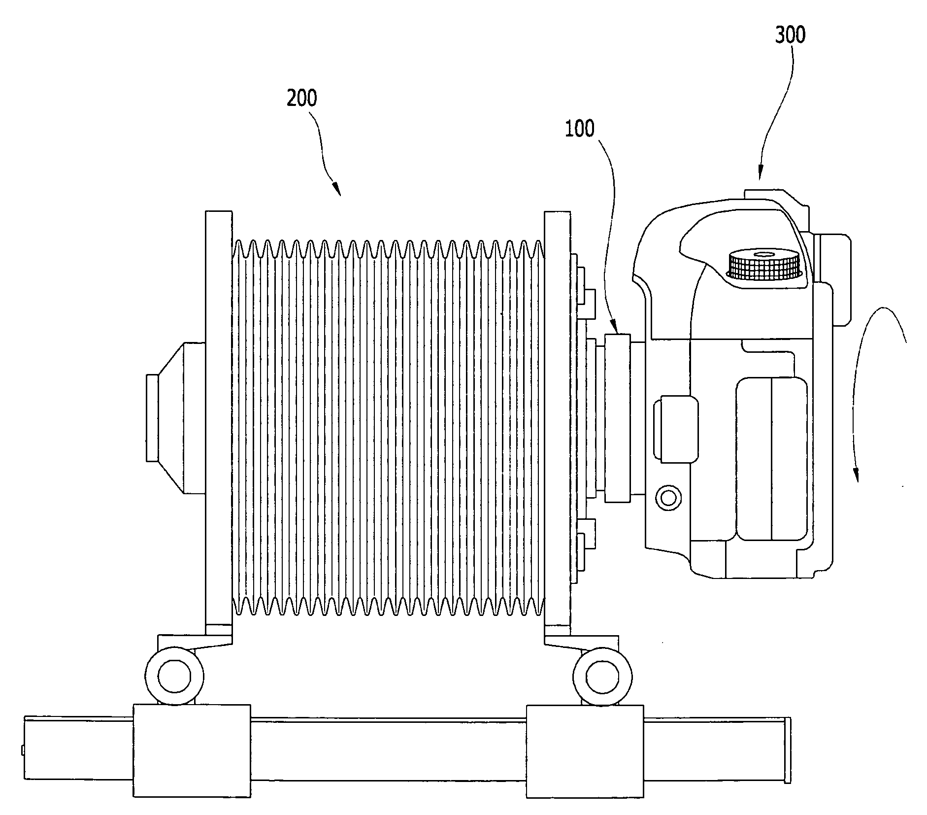
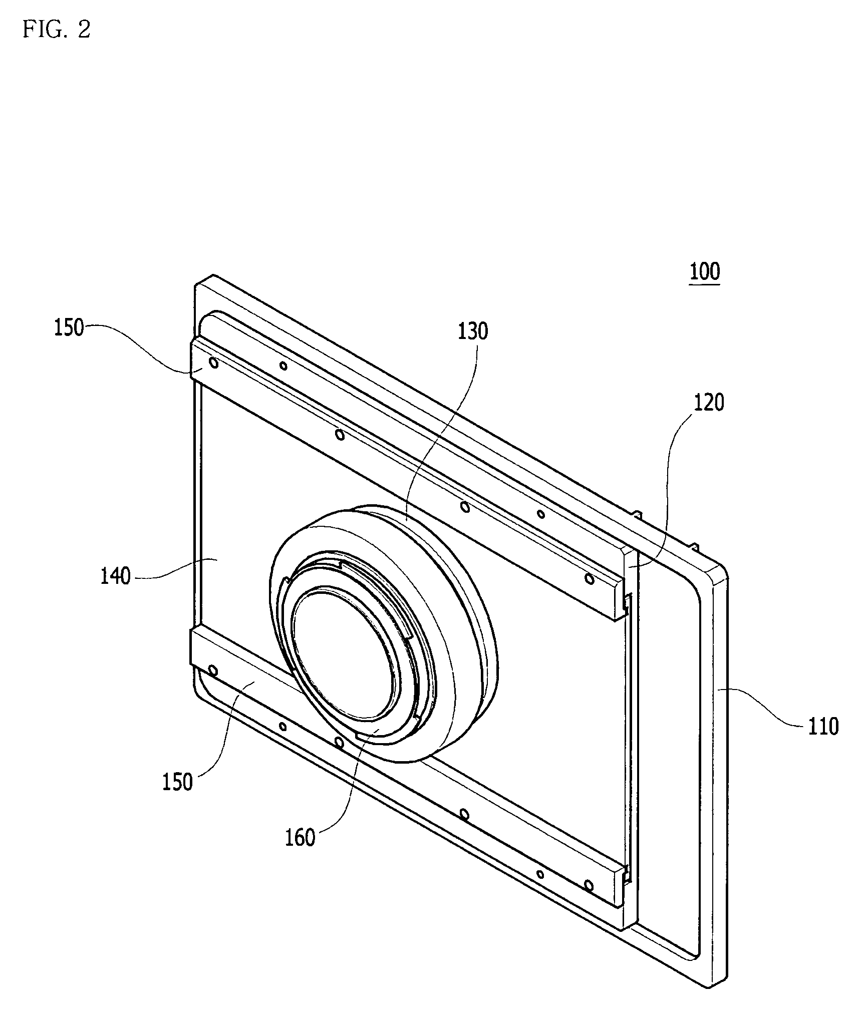
[0027]A complete embodiment of a connector panel 100 is illustrated in FIG. 2 (front view) and FIG. 5 (rear view). As shown in FIG. 1, the connector panel comprises a base panel 110, a docking panel 120, protruding pieces 130, a sliding panel 140, two guiding strips 150, and a mount ring 160.

[0028]The base panel has an overall dimension of 17.1 cm×11.9 cm, and its thickness is 0.5 cm. The size of the base panel is exactly same as the size of a film holder of a view camera, as the flat side of the base panel is to be placed on a rear standard of the view camera where a film holder is usually placed. The base panel has an opening 111 in the middle. A docking panel, which allows smooth movement for the sliding panel, is affixed to the base panel by bolts. The docking panel also has an opening 121 that conjoins with the opening of the base panel. After placing a sliding panel on top of the docking panel, the two guiding strips are affixed to the docking panel by bolts. A...


PUM


Abstract

As a back panel of a view camera, the connector panel (100) attaches a digital single lens reflex camera to a view camera. The connector panel comprises a base panel (110), sliding panel (140), protruding pieces (130), and a mount ring (160). Two guiding strips (150) are attached to the base panel, allowing the sliding panel to be shifted side-to-side. This horizontal movement produces panorama photographs with no distortions and financial burden. Moreover, photographs can be taken at various angles as the mount ring, where the DSLR camera is attached, can rotate both clockwise and counter-clockwise. Lastly, the connector panel allows view camera's images to be saved as digital images through DSLR camera's imaging sensor, such as CCD and CMOS. Hence, view camera's images become easier to be saved, edited, and developed.

Description

CROSS-REFERENCE TO RELATED APPLICATIONS[0001]Not ApplicableFEDERALLY SPONSORED RESEARCH[0002]Not ApplicableSEQUENCE LISTING OR PROGRAM[0003]Not ApplicableBACKGROUND[0004]1. Field[0005]This application relates to large format cameras, particularly to a view camera.[0006]2. Prior Art[0007]Generally cameras are classified as small, medium, and large format cameras. Among the three, large format cameras refer to cameras that use 4×5 inches sized large sheet films. Images of large format cameras are viewed through a ground glass; hence they are also called view cameras.[0008]A view camera comprises a front standard where a lens is attached, a rear standard where a photographic film holder is placed, and a flexible bellows which forms a light-tight seal between the front standard and the back standard, allowing various movements for the camera. Through these movements; such as rise, fall, shift, tilt, and swing; various framing, perspectives, and focal planes can be created.[0009]View cam...

Claims


Application Information

Patent Timeline
IPC IPC(8): H04N5/225
CPCH04N5/2253H04N23/54
Inventor CHOI, EUN JEONGLEE, JONG OK
Owner CHOI EUN JEONG
Learn More