
Electronic device for detection and storage of rds signal data

a technology of electronic devices and data, applied in the field of electronic devices, can solve the problems of preventing the storage of all necessary information, still storing information in an uncontrolled manner, and reducing the versatility of operation, and achieve the effect of increasing the versatility of operation

Inactive Publication Date: 2010-07-15
DE LORENZO LUIGI
View PDF4 Cites 0 Cited by
  • Summary
  • Abstract
  • Description
  • Claims
  • Application Information

AI Technical Summary

Benefits of technology

[0015]The object of the present invention is to overcome the above drawbacks, by providing an electronic device for detection and storage of RDS signal data that is highly efficient and relatively cost-effective.
[0016]A particular object is to provide an electronic device that allows the user to only store the RDS signal data of interest to him / her, thereby preventing the storage device from becoming saturated with data not requested by the user.
[0017]A further object of the present invention is to provide an electronic device that can interface with other external devices for displaying and / or processing of stored data in a simple and immediate manner even for inexpert users.
[0021]This may prevent the storage device from being overloaded with useless data which would cause it to become saturated in relatively little time.
[0023]Thus, the information stored in the electronic device of the invention may be easily transferred to one or more external devices for processing and / or management, such as personal computers, MP3 players, cellular phones, handheld computers and the like.
[0025]Thanks to this last feature, the electronic device may be also used in combination with radio receiver units having no RDS decoder, thereby considerably increasing their versatility of operation.

Problems solved by technology

While this solution allows text information to be displayed, such as the title or author of one or more tunes broadcast by a radio broadcasting station, it still stores information in an uncontrolled manner, also recording information of little or no interest to the user of the device.
Therefore, if the storage media does not have an adequate capacity, there will be the risk that it can become saturated in little time, thereby preventing storage of all necessary information.
Furthermore, prior art devices do not allow transfer from the storage to other apparatus for processing and management of stored information or for use of such information for management of multimedia services.

Method used


Image

  • Electronic device for detection and storage of rds signal data
  • Electronic device for detection and storage of rds signal data
  • Electronic device for detection and storage of rds signal data

Examples


Embodiment Construction

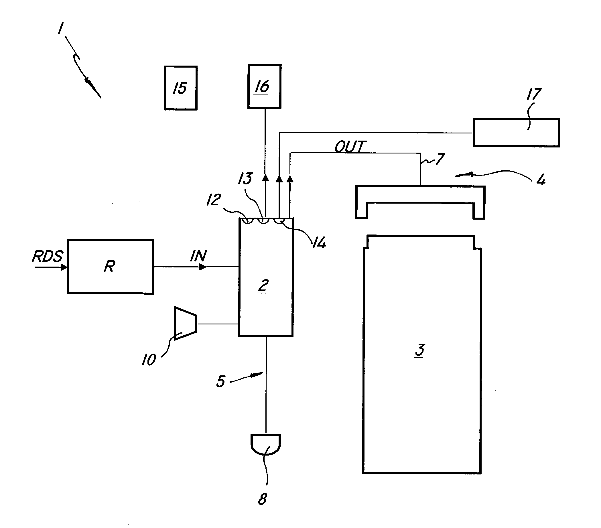
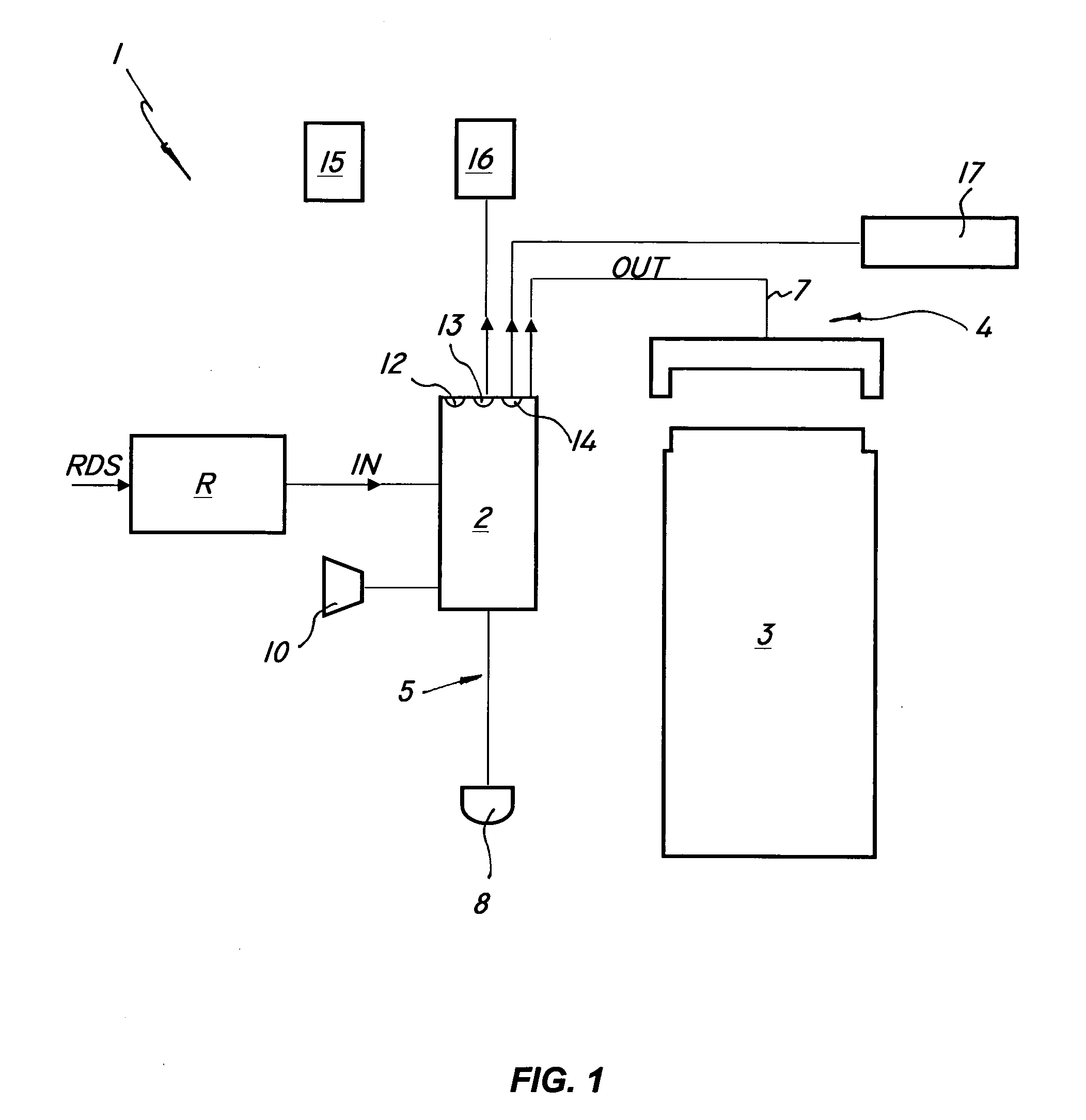
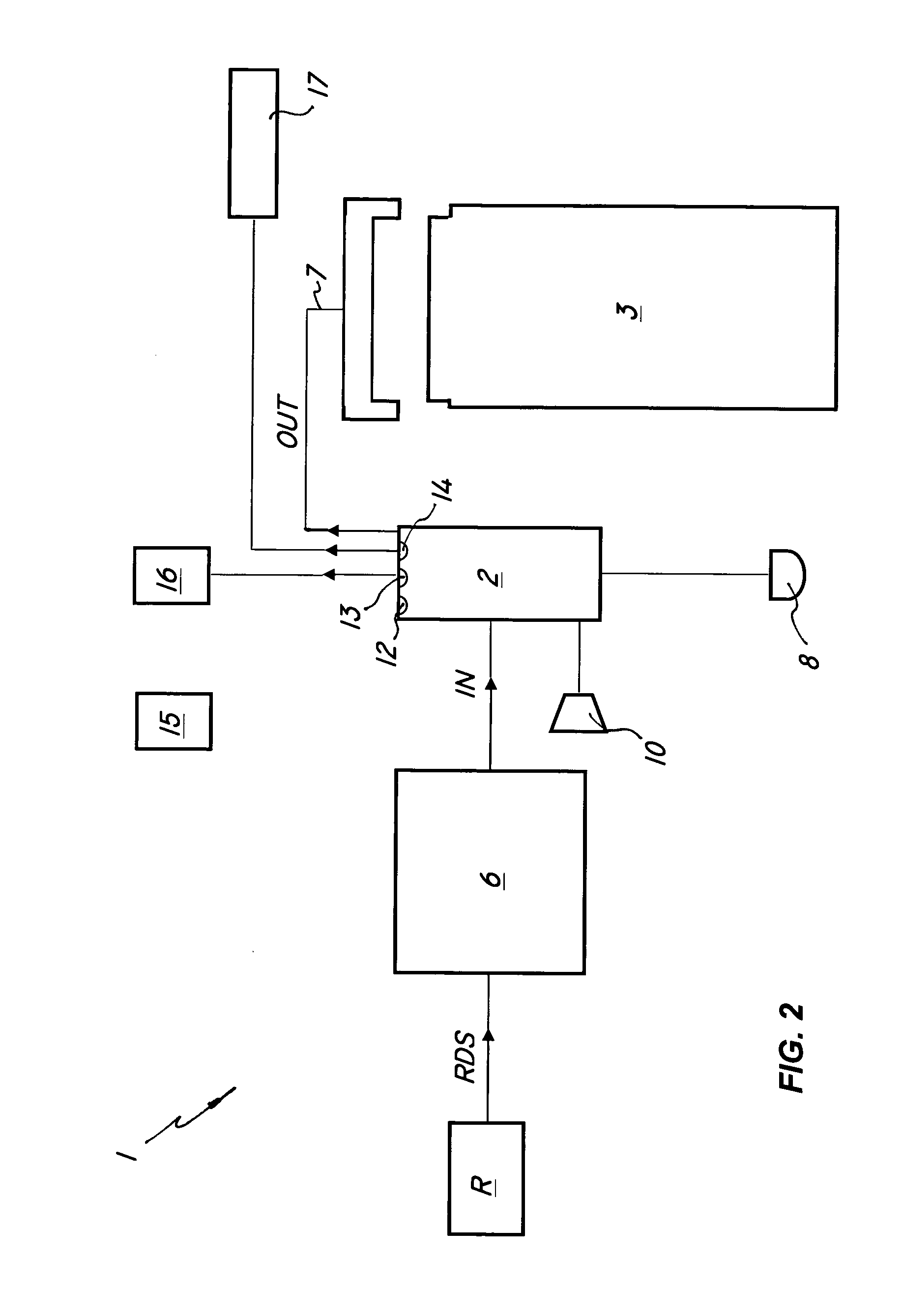
[0030]Referring to the above figures, the electronic device of the invention, generally designated with numeral 1, may be associated with a radio receiver unit R of common use, such as a radio set, a car radio or similar unit, for detecting and storing data in the RDS signal associated to the input radio signal to the radio receiver unit R.

[0031]The electronic device 1 may be incorporated in the radio receiver unit R, or associated thereto in a wholly or partially removable manner.

[0032]As diagrammatically shown in FIG. 1, the electronic device of the invention comprises a first microprocessor unit 2 which is designed to be connected to an external radio receiver unit R adapted to receive a radio signal in any frequency band and to extract the RDS signal therefrom.

[0033]The first microprocessor unit 2 detects and processes one or more data signals IN associated to the input RDS signals from the radio receiver unit R and then generates an output data signal OUT directed to a main sto...


PUM


Abstract

An electronic device for detection and storage of RDS signal data comprises a first microprocessor unit for detecting and processing a data signal (IN) associated to a RDS signal received from a radio receiver unit (R). The first microprocessor unit has at least one output data signal (OUT), a main storage device for storing the output data signal (OUT) from the first microprocessor unit, transmission means for transmitting the output signal (OUT) between the first microprocessor unit and the main storage device. Normally open switch means are provided, which are designed to be operated by a user to selectively enable transmission of the output signal (OUT) to the main storage device.

Description

FIELD OF THE INVENTION[0001]This invention finds application in the field of electronic devices and particularly relates to an electronic device for detection and storage of data in a RDS signal associated to a radio signal.BACKGROUND ART[0002]RDS (Radio Data System) signal is known to be an auxiliary encoded signal which accompanies a normal radio signal to allow identification or transmission of control data or messages at the same time as the radio program with which it is associated.[0003]According to a well-established standard, RDS signal is a continuous string of binary data organized in 104 bits-long groups, each divided into four blocks of 26 bits. Each block is in turn divided into a first 16-bit portion, containing the encoded information to be transmitted and a second 10-bit portion that is used for checking and correcting the transmitted data.[0004]The codes associated to a RDS signal can be used as an aid for tuning the receiver, such as the PI code for broadcast progr...

Claims


Application Information

Patent Timeline
Patent Type & Authority Applications(United States)
IPC IPC(8): H04B1/02
CPCH04H20/34H04H2201/13H04H60/27
Inventor DE LORENZO, LUIGI
Owner DE LORENZO LUIGI
Learn More