Gear Trains Employing Magnetic Coupling
a technology of magnetic coupling and gear train, applied in the direction of permanent magnet clutch/brake, dynamo-electric brake control, dynamo-electric machines, etc., can solve problems such as wear and breakag
- Summary
- Abstract
- Description
- Claims
- Application Information
AI Technical Summary
Problems solved by technology
Method used
Image
Examples
example i
III. Example I
“Ring and Planetary Gear” System
[0042]The example given in this section is one that can be employed, e.g., in a wind turbine. In such a case the gear box would be used to increase the rotation speed of the wind turbine (of order 20 RPM in the example) up to a higher speed in order to drive a generator. Depending on the parameters of the generator, a second Halbach array gear box might be used in series to achieve the finally desired rotation speed. However, because of the increased input rotational speeds involved, the second gear box would expected to be substantially smaller in size than the first gear box.
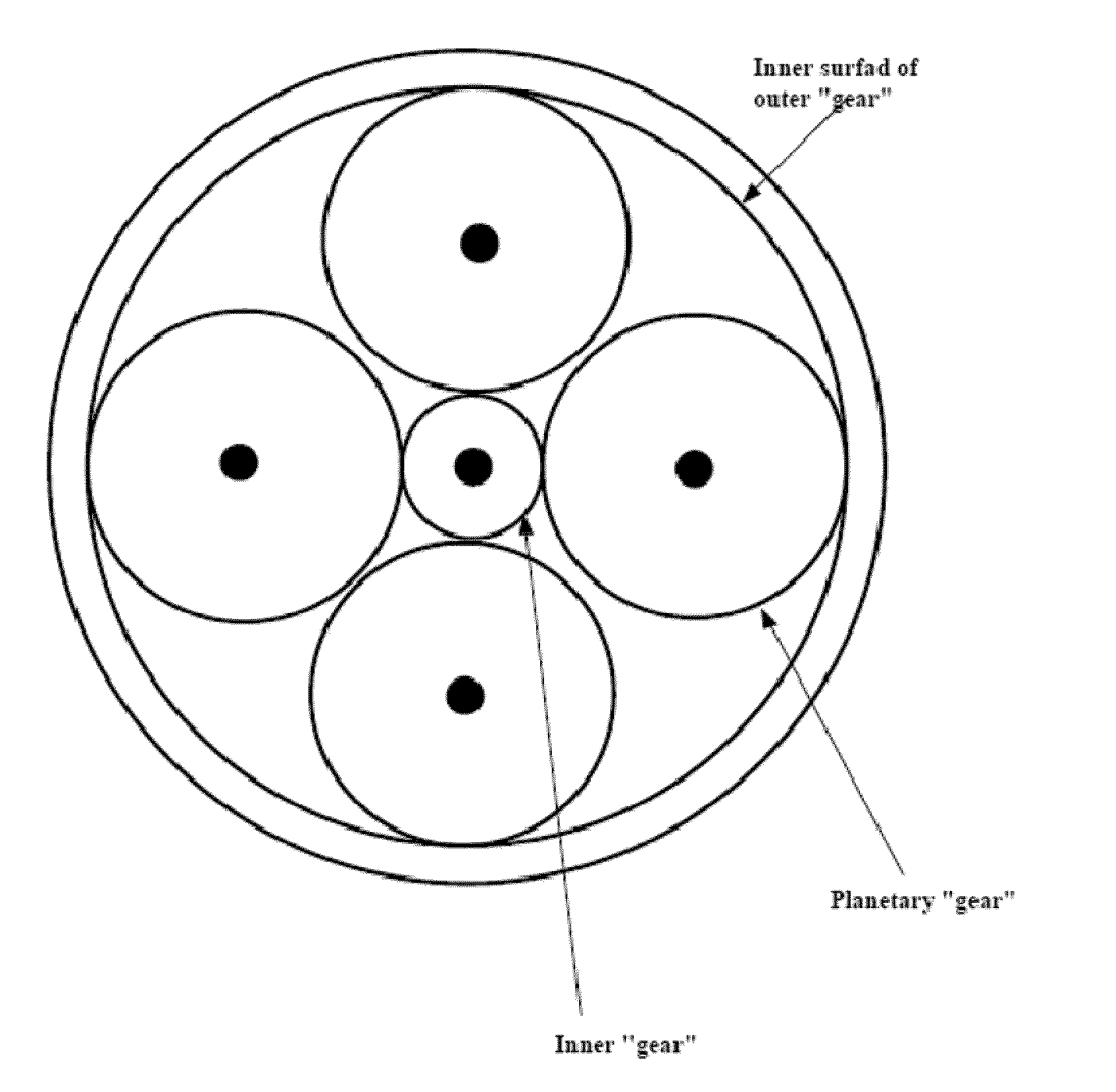
[0043]FIG. 5 is a schematic drawing of the Example I gear box. This embodiment includes an outer gear 20 having an inner surface on which Halbach arrays are located. Planetary gears 22-25 are within the ring formed by outer gear 20. An inner gear 28 is centrally located. Each of the “gears” shown is assumed to have an elongated Halbach array on its cylindrical work...
example ii
IV. Example II
Ring gear and off-center gear; eddy-current brake
[0050]This example illustrates a gear train where the curvature of both gears has the same sign so that the effective area of interaction between the two gears is increased relative to that which would apply if the two curvatures were of opposite sign, as is the case for the planetary gears and the central gear of the previous example. It is also represents a configuration that would permit the use of several off-center gears, in applications such as a wind turbine where the ring gear, driven by the wind turbine, would drive several smaller generators. FIG. 9 is a schematic drawing of the configuration with one off-center gear 30 driven by the ring gear 32. The gear ratio in this case is 1:5, i.e., the rotation speed of the inner gear is five times that of the ring gear.
[0051]FIG. 10 shows the calculated maximum azimuthal force per unit area as a function of the arc angle relative to the position of minimum gap between t...
PUM
 Abstract
Description
Claims
Application Information
 - R&D
- Intellectual Property
- Life Sciences
- Materials
- Tech Scout
- Unparalleled Data Quality
- Higher Quality Content
- 60% Fewer Hallucinations
Browse by: Latest US Patents, China's latest patents, Technical Efficacy Thesaurus, Application Domain, Technology Topic, Popular Technical Reports.
© 2025 PatSnap. All rights reserved.Legal|Privacy policy|Modern Slavery Act Transparency Statement|Sitemap|About US| Contact US: help@patsnap.com


