
Gasket Distributor

Inactive Publication Date: 2010-07-15
OUTOTEC OYJ
View PDF12 Cites 0 Cited by
  • Summary
  • Abstract
  • Description
  • Claims
  • Application Information

AI Technical Summary

Benefits of technology

[0004]Hence there is a need for a flange joint that has a special gasket for fluid distribution in ord

Problems solved by technology

While moving solids inside an object or an apparatus or inside a part of apparatus (for example, in a pipeline or similar with fluid for the sake of transportation, sizing or classifying), problems occur when for some reason the fluid moves forward but does not carry the solid material with.

Method used


Image

  • Gasket Distributor
  • Gasket Distributor
  • Gasket Distributor

Examples


Embodiment Construction

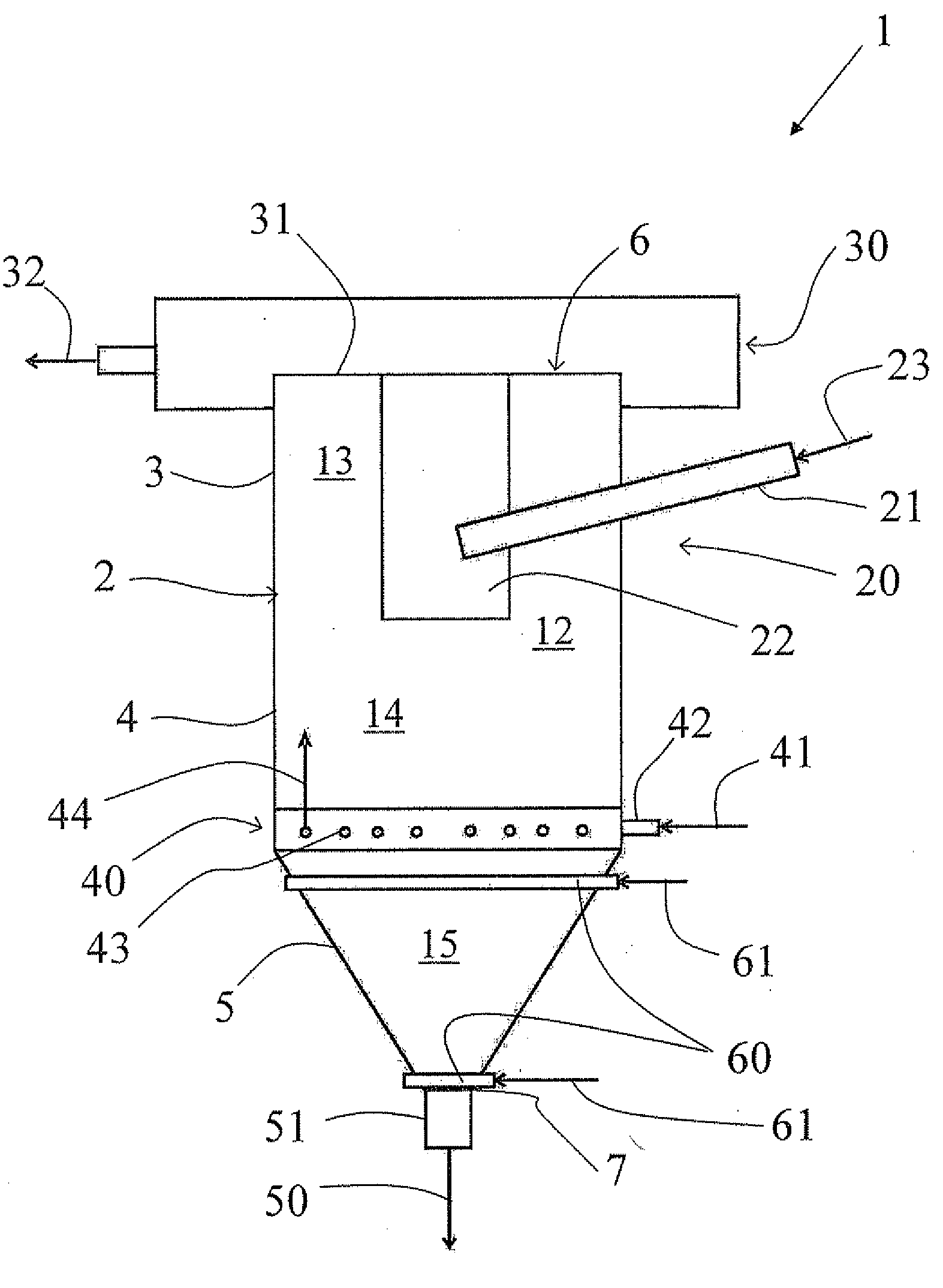
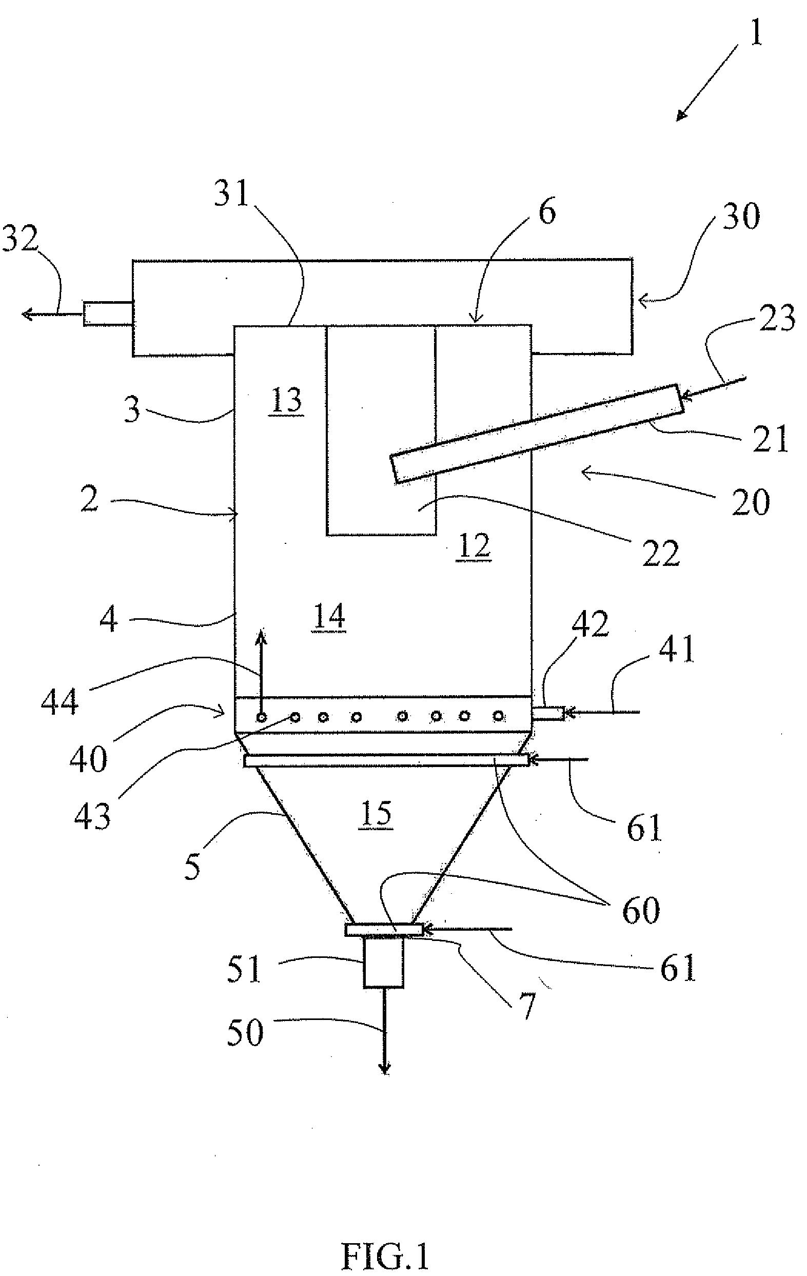
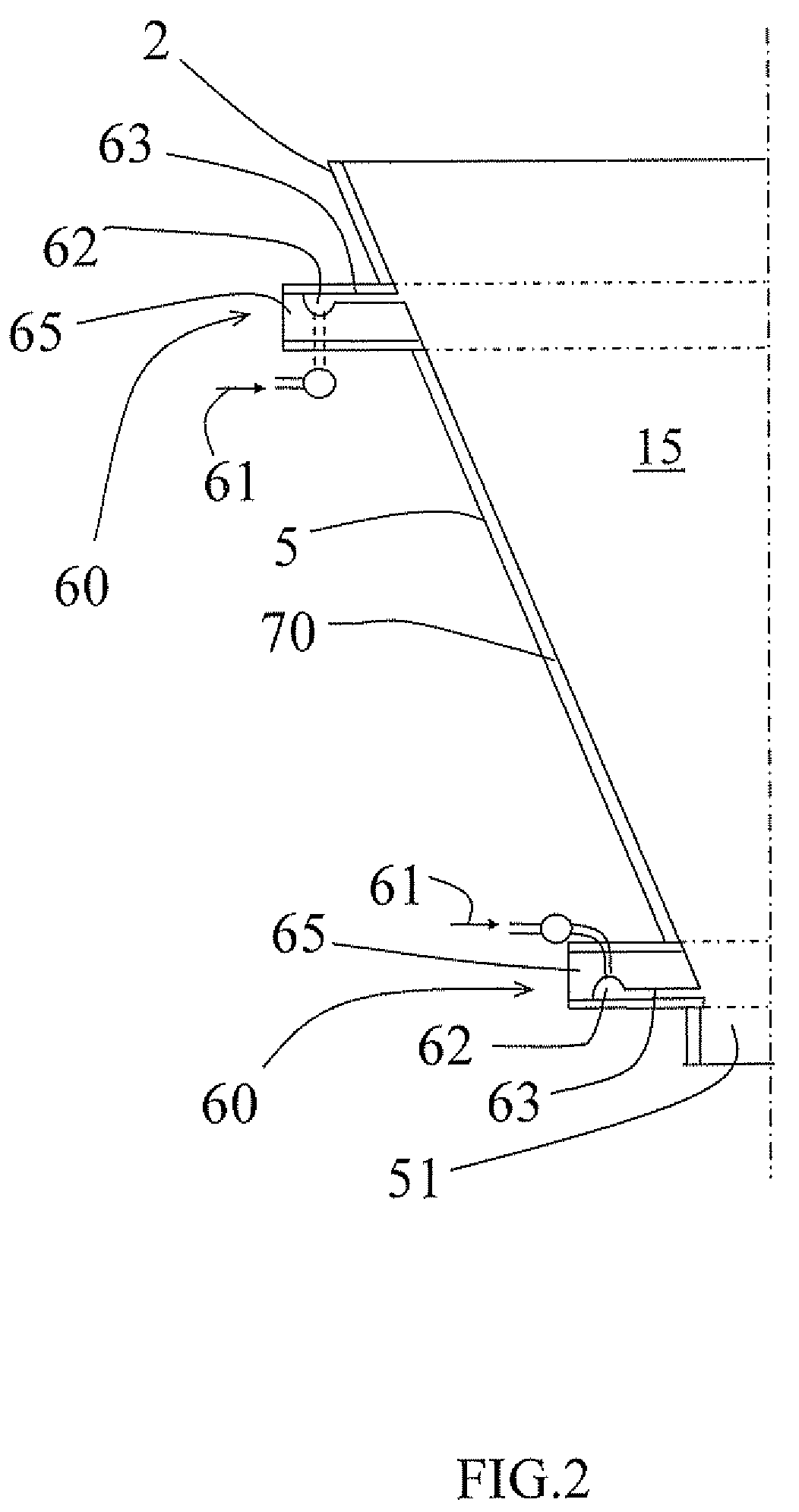
[0022]In the FIGS. 1 and 2 the hindered-bed settler 1 for separating particles in hydrous slurry and preferred embodiments and variations of the hindered-bed settler 1 will be described.

[0023]The FIG. 1 shows a general view of a hindered-bed settler 1. The hindered-bed settler 1 comprises a body 2 defining an inner space 12. The body 2 of the hindered-bed settler 1 is advantageously either circular or rectangular and having an upper part 3, a middle part 4 and a lower part 5 and an open top 6 and a bottom 7 defining the inner space 12 with an upper portion 13, a middle portion 14 and a lower portion 15. At the bottom 7 of the settler 1 is an outlet valve 51 through which coarse feed 50 flows. The coarse feed 50 flow is indicated by an arrow.

[0024]The hindered-bed settler 1 comprises also a feed well means 20 for introducing hydrous slurry into the inner space 12 of the body 2. The feed well means 20 comprise an inlet pipe 21 and a feed well 22. Hydrous slurry 23 enters the inlet pip...


PUM

PropertyMeasurementUnit
Flexibilityaaaaaaaaaa

Abstract

A flange joint for connecting two objects in a fluid connection so that fluid can flow between the objects. The flange joint has a gasket and the gasket is installed in the flange joint. The flange joint has at least one channel for feeding additional fluid from outside of the flange joint through the gasket into fluid flowing between the two objects.

Description

FIELD OF THE INVENTION[0001]The invention relates to a flange joint for connecting two objects in a fluid connection so that fluid can flow between the objects, to a hindered-bed settler for separating particles of hydrous slurry, and also to a method for preventing clogging in an apparatus comprising several objects between which fluid flows.BACKGROUND OF THE INVENTION[0002]While moving solids inside an object or an apparatus or inside a part of apparatus (for example, in a pipeline or similar with fluid for the sake of transportation, sizing or classifying), problems occur when for some reason the fluid moves forward but does not carry the solid material with. The motion of the solid material then slows down and finally stops. The solid material starts to accumulate and ends up with blocking the object.[0003]For the above mentioned reason water should be added on the way continuously for process reasons or temporarily for improved material flow, to open a blockage or to add for ex...

Claims


Application Information

Patent Timeline
IPC IPC(8): B01D21/00F16L23/16
CPCB03B5/623F16L23/16F16J15/064B03B5/66
Inventor NIITTI, TIMO
Owner OUTOTEC OYJ
Learn More