Eureka AIR delivers breakthrough ideas for toughest innovation challenges, trusted by R&D personnel around the world.

System and method for monitoring operation of vehicles

a vehicle and monitoring system technology, applied in the field of vehicle monitoring system and method, can solve the problems of wide margins of error in simulation of real-life duty cycle by the best available and most sophisticated techniques, and the inability to accurately reflect the actual conditions encountered by particular vehicles in servi

Active Publication Date: 2010-07-08
NEW FLYER INDS CANADA ULC
View PDF46 Cites 256 Cited by
  • Summary
  • Abstract
  • Description
  • Claims
  • Application Information

AI Technical Summary

Benefits of technology

[0008]Data collected from the use of test vehicles in test conditions is in many cases not representative of the actual operating conditions encountered by specific vehicles in the field, which conditions are of greatest interest in monitoring and controlling fleet operations and management processes. Collecting data from vehicles in the field (i.e., in service) can allow the operating conditions of specific individual vehicles to be recorded, and the effect of the conditions on such vehicles to be processed and considered either at leisure or in real time. This may also allow for data from specific transit routes, or associated with individual operators (e.g., drivers) of transit vehicles to be collected and analysed, and maintenance, repair, and / or corrective action to be scheduled and conducted.
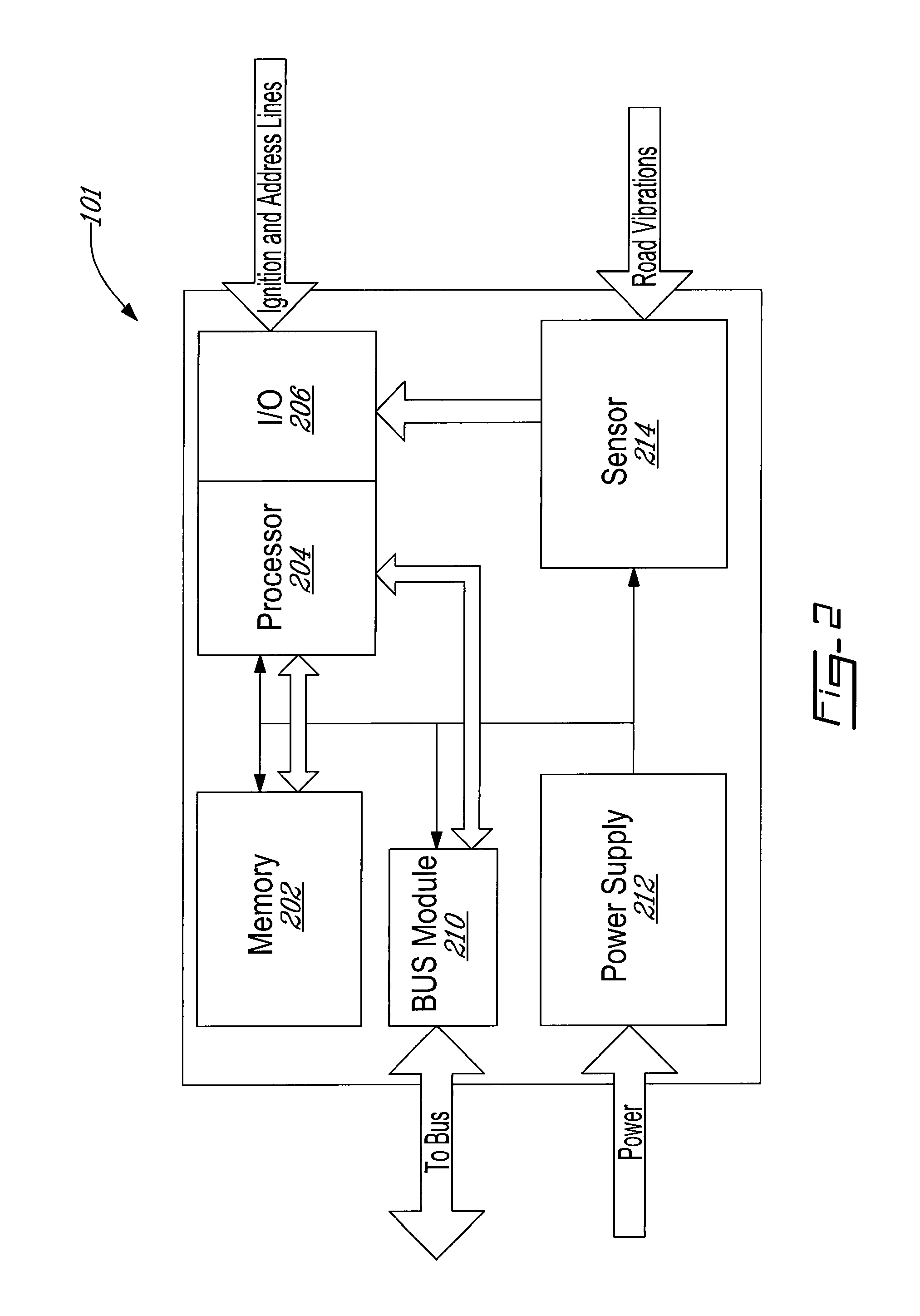
[0009]In one aspect, the invention provides devices attachable to or otherwise installable in transit and other vehicles and useful for acquiring data related to the structural loading or other operational aspects of transit or other vehicles. Such a device may comprise one or more sensors configured for sensing shocks, temperatures, pressures, humidities, impacts, vibrations, speed, torque and / or other structural events, or other operational conditions or parameters, experienced by or associated with the vehicle, and / or the structural or other system response of the vehicle thereto, and for providing corresponding output signals; one or more data processors configured for processing said output signals to generate data useful in determining response of the vehicle to such structural events; and memory usable by the data processor(s) for storing the data useful in determining structural response of the vehicle. Signals generated by such sensors may be processed by the one or more data processors, and / or by other data processors, for analyzing the structural loading and / or response of such vehicles or systems to structural or operational events experienced by the vehicle(s). For example, signals corresponding to accelerations and / or strains experienced by the vehicles may be used in determining the effect of such structural events on the fatigue life of the vehicles, or portions thereof, and / or for assessing or investigating damage to the vehicle(s) or the possibility thereof. As a further example, engine or air-conditioning system parameters such as temperature(s), humidities, pressure(s), rotational speeds (RPMs), torques, etc., may be measured and used in determining the status or operational history of such engines, environmental control systems, etc. In analyzing acquired signals to make such determinations, rain-flow and other peak-counting or level-crossing algorithms may be advantageously employed.

Problems solved by technology

However, such testing does not always accurately reflect the conditions actually encountered by particular vehicles in service.
For example, one major unknown factor in structural design integrity is the conditions of the streets on the routes actually taken by any given bus(es) in service.
As a result, simulation of real-life duty cycles by the best available and most sophisticated techniques can be in error by wide margins (for example, 50%-100%, or more).

Method used


Image

  • System and method for monitoring operation of vehicles
  • System and method for monitoring operation of vehicles
  • System and method for monitoring operation of vehicles

Examples


Embodiment Construction

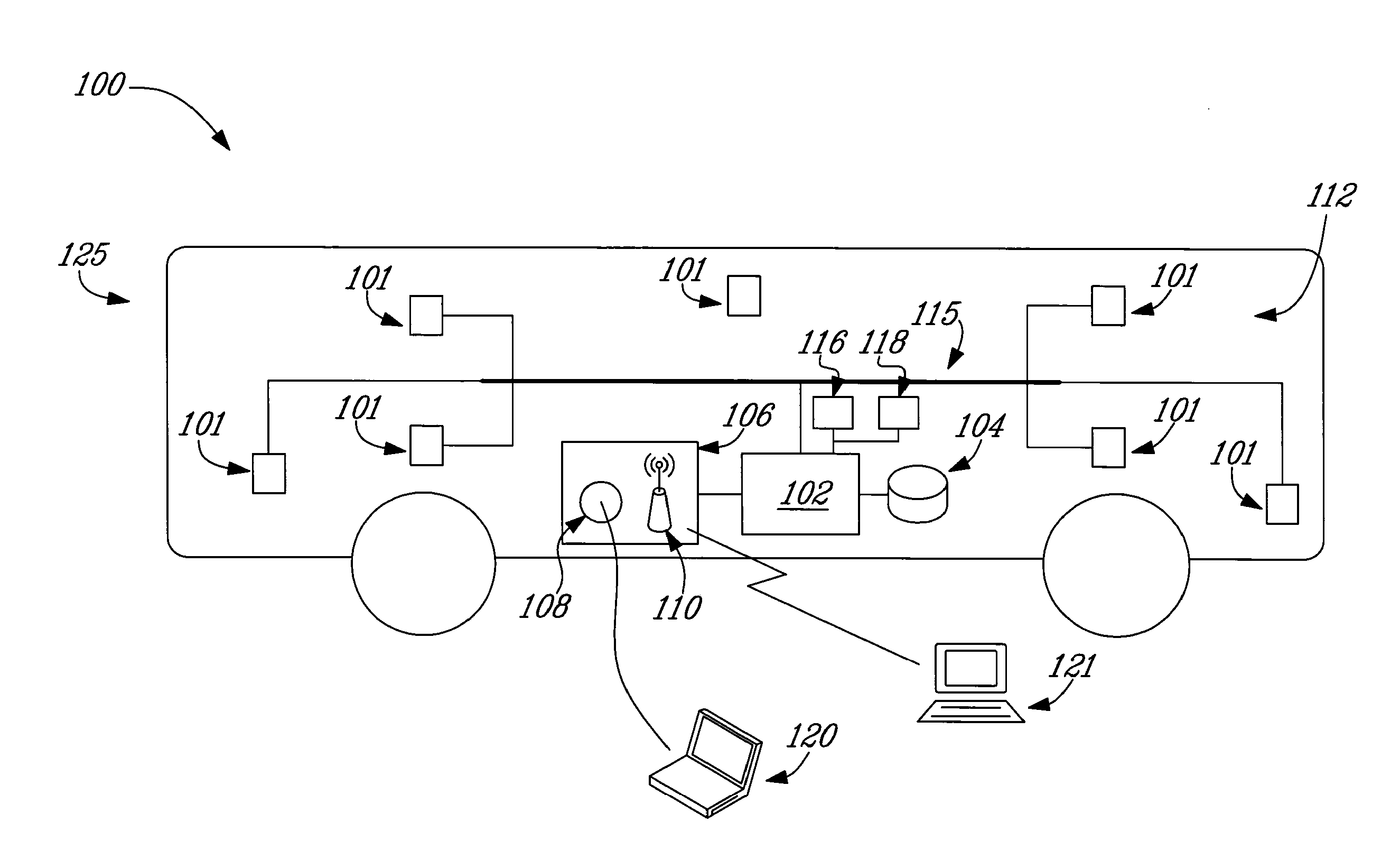
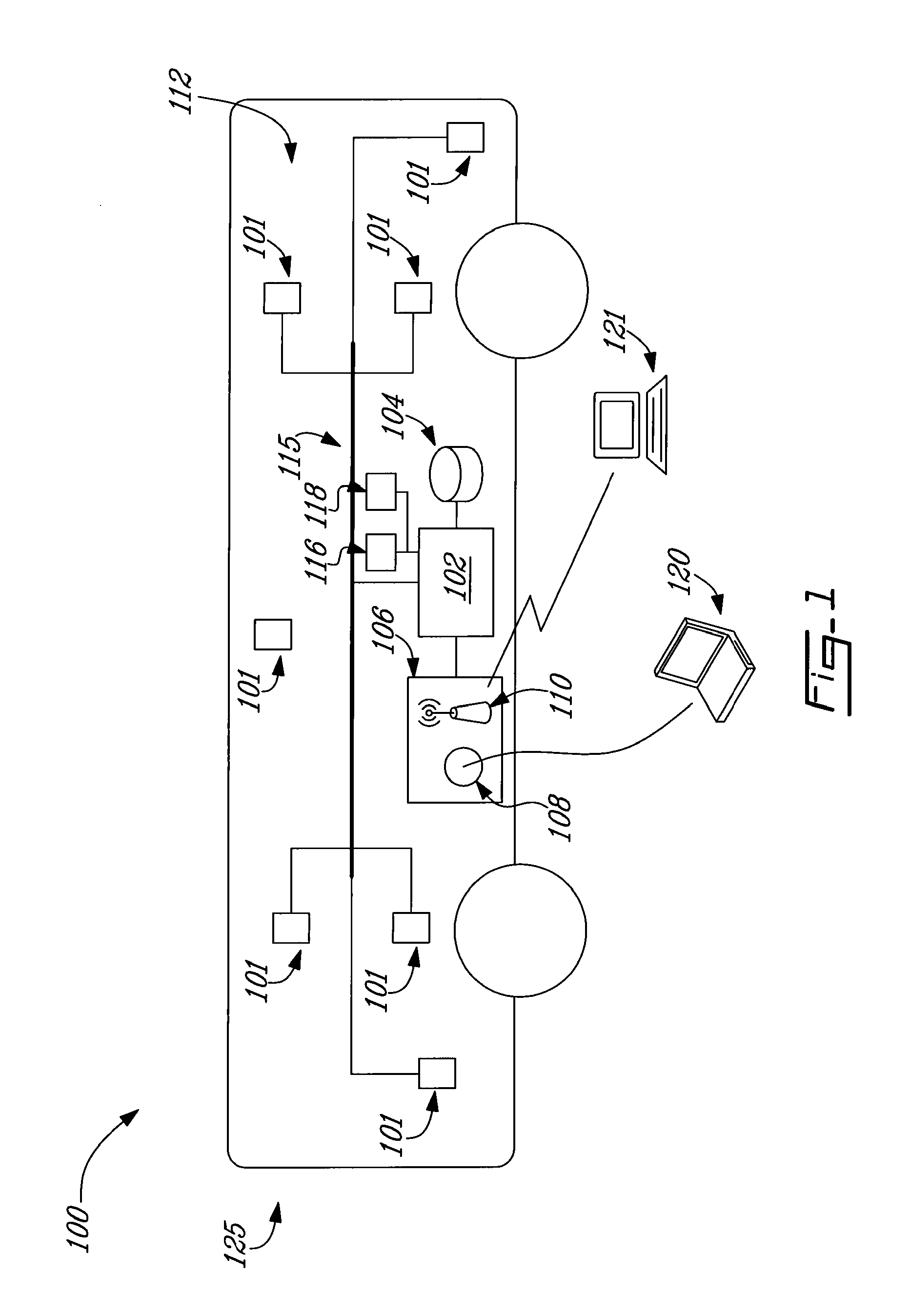
[0026]FIG. 1 shows, in block diagram form, an example of a system 100 for gathering data relating to the structural loading or other operational condition(s) of a transit or other vehicle in accordance with the invention. In the embodiment shown, system 100 is installed in a vehicle 125 and is adapted to interact with one or more diagnostic / maintenance tools 120,121 through, for example, the exchange of various command and data signals. System 100 comprises a data acquisition system 112 which, in the embodiment shown, includes one or more on-board (or “central”) system controllers 102, memory(ies) 104, data bus(es) 115, input / output component(s) 106, and one or more data acquisition devices 101 which may be attached or attachable to various portions and / or systems of the vehicle 125.

[0027]Data acquisition device(s) 101 may be configured to gather, and process, communicate, and / or store, data relating to the structural loading or other operational condition(s) of a vehicle 125 to whi...


PUM


Abstract

Systems, methods, devices, and computer programming products useful for the gathering and use of data relating to structural loading and other operational use of transit and other vehicles, and their systems. Systems according to the invention can, for example, comprise one or more data acquisition devices such as strain gauges, accelerometers, or other sensors; data processors; memories; and communications systems. Such systems, methods, and programming are useful in a wide variety of ways, including, for example, monitoring the structural status and use of vehicles and their systems, including fatigue other operational analyses; gathering and applying data useful in the maintenance of such vehicles and the routes they travel; monitoring the use / abuse of such vehicles by operators and other individuals; reporting traffic events or anomalies; and routing transit and other vehicles around such events or anomalies. Rainflow, level-crossing and other peak-counting or event-counting algorithms are applied to advantage, such that required data storage is greatly reduced, and life-long monitoring is feasible.

Description

CROSS REFERENCE TO RELATED APPLICATIONS[0001]This application claims the benefit of, and by this reference incorporates the entirety of, U.S. Provisional Patent Application Ser. No. 61 / 143,325, filed 8 Jan. 2009 and entitled STRUCTURAL FATIGUE DATA LOGGER.FIELD OF INVENTION[0002]The present application relates to systems, methods, and computer programming structures and products useful for monitoring structural loading and / or performance of engines and other systems in vehicles, and particularly in buses and other public transit vehicles, and for using data so monitored.BACKGROUND OF THE INVENTION[0003]Currently, public transit vehicle manufacturers use finite element analysis (FEA) and road testing to verify the structural integrity of their vehicles during the design and testing phases of vehicle development. However, such testing does not always accurately reflect the conditions actually encountered by particular vehicles in service. For example, one major unknown factor in struc...

Claims


Application Information

Patent Timeline
Patent Type & Authority Applications(United States)
IPC IPC(8): G06Q50/00G06F7/00G06Q10/00G01C21/00G06N5/02
CPCG06Q10/04G06Q10/06G07C5/00G08G1/20G06Q50/30G06Q50/40
Inventor NAYLOR, DAVID GLEN
Owner NEW FLYER INDS CANADA ULC
Why Eureka
Eureka Blog
Learn More