
Remote Control System and Relay Unit

Inactive Publication Date: 2010-07-08
YAMAHA CORP
View PDF7 Cites 1 Cited by
  • Summary
  • Abstract
  • Description
  • Claims
  • Application Information

AI Technical Summary

Benefits of technology

[0008]The present invention aims at providing a remote control system that can prevent a system from running out of control even when an end command cannot be received.
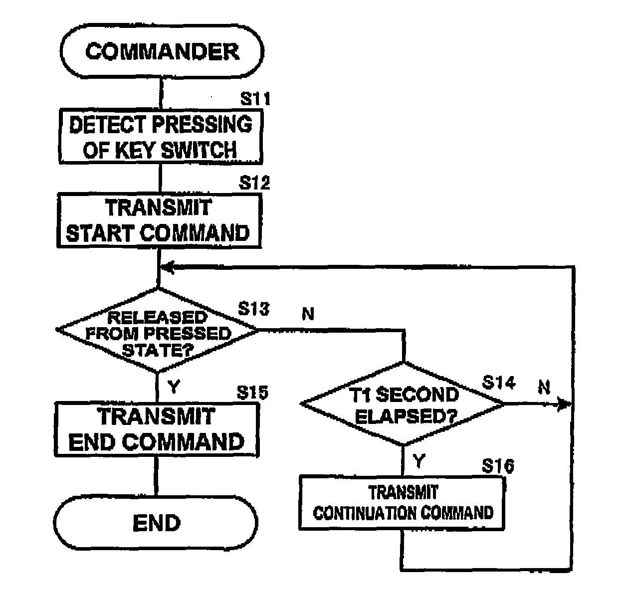
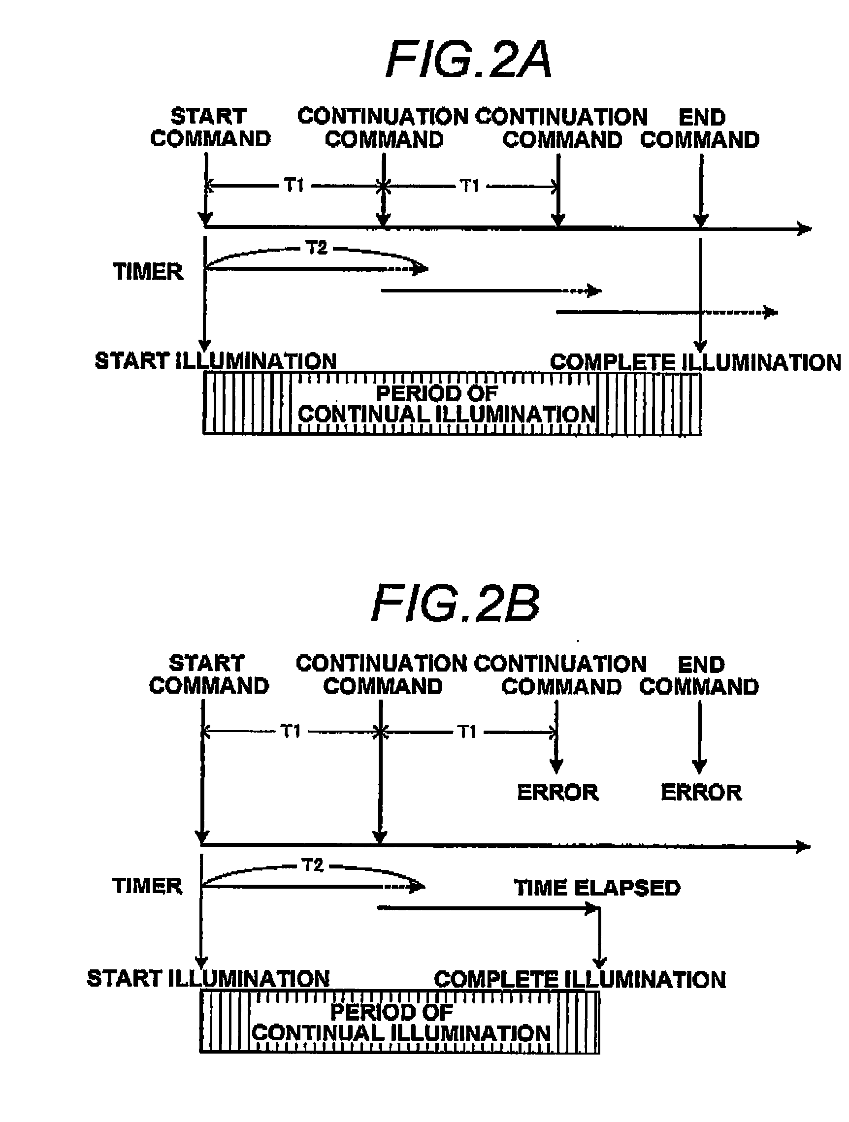
[0017]According to aspects of the present invention, even when receipt of an end command has ended in failure, transmission of a control signal will be stopped if the next command is not received even after elapse of a specific period of time. Therefore, it is possible to prevent a system from running out of control, such as uncontrollable raising of the volume. Since a continuation command is transmitted at specific periods of time, even when; for instance, a volume UP key is pressed for a long period of time, it is possible to effect control commensurate with the period of time during which the key is pressed.

Problems solved by technology

Meanwhile, since wireless LAN communication is effected by means of a protocol, such as a TCP / IP, difficulty is encountered in continually performing processing for a period of time, such as continual transmission of a remote control code.
However, when the relay unit becomes unable to receive an end command for reasons of any communication failure after receipt of a start command, the aforementioned communication pattern raises a problem of continual transmission of the remote control code being continued without interruption.
For instance, when an end command cannot be received in the course of continual transmission of a remote control code for turning up the volume, the audio equipment will be commanded to turn up the volume endlessly, so that the volume is turned up uncontrollably.

Method used


Image

  • Remote Control System and Relay Unit
  • Remote Control System and Relay Unit
  • Remote Control System and Relay Unit

Examples


Embodiment Construction

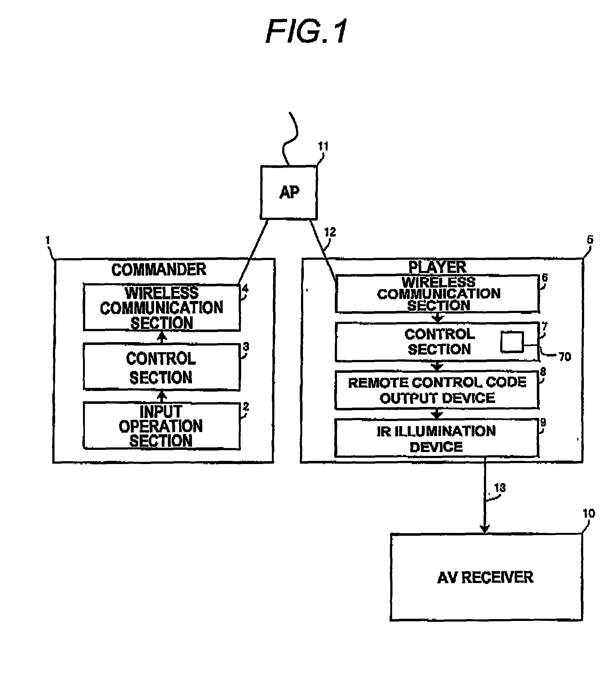
[0023]FIG. 1 is a block diagram of an audio system according to an embodiment of the present invention. The audio system includes a commander 1 that is a device for transmitting a command message via a wireless LAN 12; a player 5 that has, as a relay unit, a function of receiving a command message from the commander 1 and outputting a remote control code corresponding to the command message by means of an infrared ray, and an AV receiver 10 serving as a device to be controlled that receives light of an infrared remote control code and that performs operation corresponding to the remote control code.

[0024]The commander 1 includes a user interface and transmits a command message conforming to user's operation to the wireless LAN 12. The player 5 has a function of a wireless LAN that plays back contents produced by a plurality of pieces of source equipment. The AV receiver 10 has a function of a power amplifier that amplifies a content played back by the player 5 and emits the thus-amp...


PUM


Abstract

A remote control system includes a commander, a device to be controlled, and a relay unit. The commander transmits a start command and an end command, and a continuation command at intervals of first specific time after transmission of the start command until the end command is transmitted. The relay unit includes a control unit that causes a control signal transmission unit to start transmitting the control signal in response to receipt of the start command and that causes the control signal transmission unit to stop transmitting the control signal in response to receipt of the end command. The control unit causes the control signal transmission unit to stop transmitting the control signal when the next command is not received even after elapse of a second specific time since the command is received, the second specific time being longer than the first specific time.

Description

BACKGROUND OF THE INVENTION[0001]1. Technical Field[0002]The present invention relates to a remote control system in which a commander controls a device to be controlled via a relay unit.[0003]2. Background Art[0004]Many pieces of audio equipment are remotely controllable by means of an infrared remote control code. A recently-proposed audio system is equipped with a relay unit that transmits an infrared remote control code to audio equipment, that has a wireless LAN function, and that is disposed in the vicinity of the audio equipment, and that controls the audio equipment by a commander having a wireless LAN function.[0005]When audio equipment is remotely controlled in connection with; for instance, turning up / down of the volume, fast forward / fast rewind of a content to be played back, and the like, a remote control code is continually transmitted for a predetermined period of time, thereby turning up or down the volume or fast forwarding or rewinding a content to a desired extent...

Claims


Application Information

Patent Timeline
IPC IPC(8): G06F17/00G05B11/01H04N5/00H04Q9/00
CPCH04N21/42204H04N21/42219H04N2005/4433H04N21/41265H04N21/4227
Inventor SUYAMA, AKIHIKOKAWASHIMA, MASATOSHI
Owner YAMAHA CORP
Learn More