Retaining structure for removably mounting a surfboard fin

a technology for retaining structures and surfboards, applied in the field of fin construction, can solve problems such as affecting the appearance of apertures in a negative way

Inactive Publication Date: 2010-07-08
YEH TZONG IN
View PDF13 Cites 12 Cited by
  • Summary
  • Abstract
  • Description
  • Claims
  • Application Information

AI Technical Summary

Benefits of technology

[0008]Broadly stated, the present invention is directed to a retaining structure for removably mounting a surfboard fin. The retaining structure includes a mounting base, a fin member, and two suppressing mechanisms. The mounting base is firmly secured within a cavity in the undersurface of a surfboard. Moreover, the mounting base has a receptacle and two holding portions adjacent to opposite ends of the receptacle. The fin member has a connecting section and a body section extending from the connecting section. The connecting section is to be embedded in the receptacle of the mounting base. The body section protrudes outside the undersurface of the surfboard and has its front and rear ends inclined outwardly. In particular, each of the two suppressing mechanisms is detachably mounted on the respective holding portion of the mounting base and includes a block. Specifically, one of the blocks defines a recess in a side thereof according to the slope of the inclined front end of the body section of the fin member while the other block defines a recess in a side thereof corresponding to the slope of the inclined rear end of the body section in such a way that the inclined front and rear ends of the body section can be fitted in the recesses of the blocks and suppressed by the blocks and thereby be secured onto the mounting base.

Problems solved by technology

Although the fin may be affixed to the underside of the watercraft easily via the screws, the apertured flange affects the appearance in a negative way.

Method used


Image

  • Retaining structure for removably mounting a surfboard fin
  • Retaining structure for removably mounting a surfboard fin
  • Retaining structure for removably mounting a surfboard fin

Examples


Embodiment Construction

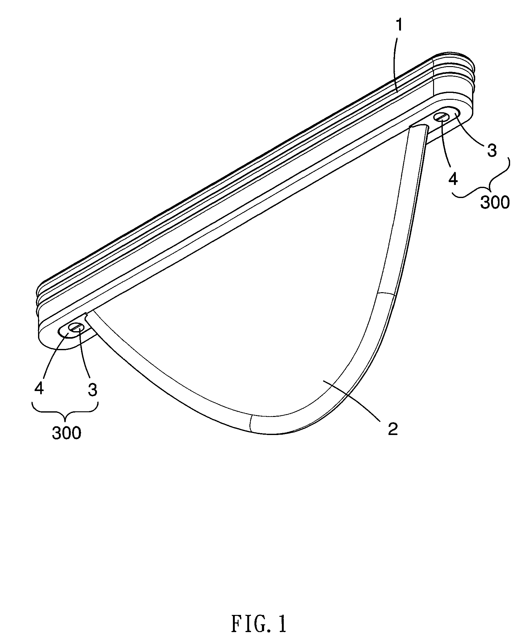
[0019]Referring now to the FIG. 1, a fin retaining structure is shown having a mounting base 1, a fin member 2 and two suppressing mechanisms 300. The mounting base 1 is to be firmly secured within a cavity in the undersurface of a surfboard, as shown in FIG. 4. Each of the suppressing mechanisms 300 includes a block 3 and a fixing part 4. The fin member 2 is attached to the mounting base 1 with the help of the two suppressing mechanisms 300.

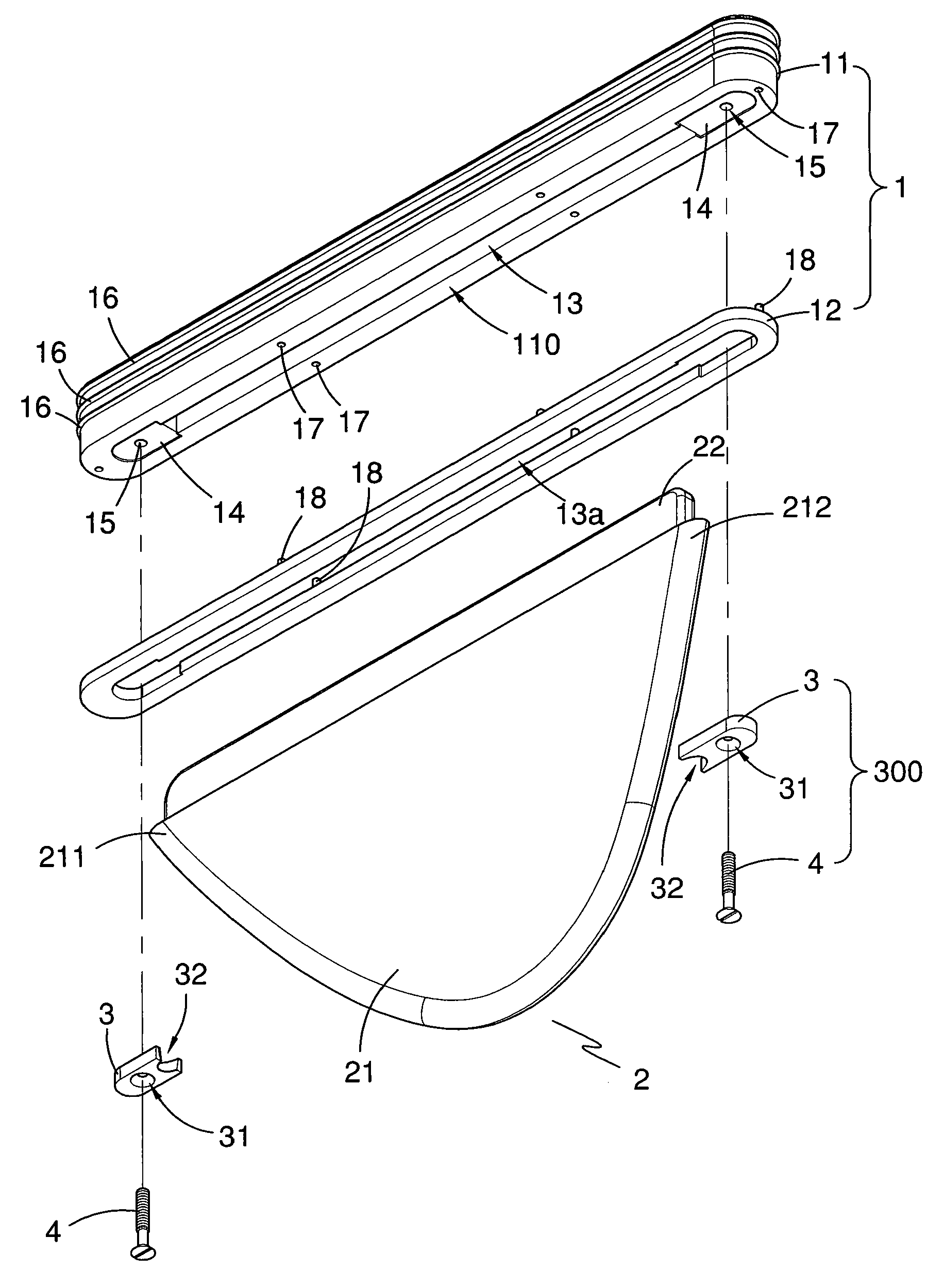
[0020]As shown in FIG. 2, the mounting base1 includes a base portion 11, a patch plate 12 and a receptacle (to be described hereinafter). The base portion 11 is fitted in a main upper portion of the cavity (see FIG. 4) and has a channel 13 and two holding portions 14 adjacent to opposite ends of the channel 13. Each of the holding portions 14 of the base portion 11 defines a fixing hole 15, such as a threaded hole, for reception of the fixing part 4. In addition, a plurality of ribs 16 is arranged around the base portion 11 to provide relatively...


PUM


Abstract

A retaining structure for a surfboard fin includes a mounting base secured in the undersurface of a surfboard, a fin member and two blocks. The mounting base has a receptacle and two holding portions. The fin member has a connecting section to be embedded in the receptacle of the mounting base and a body section extending from the connecting section. The body section of the fin member protrudes outside the undersurface of the surfboard and has front and rear ends inclined outwardly. Each block is detachably mounted on the respective holding portion of the mounting base and defines a recess in a side according to the slope of the respective inclined end of the body section so that the inclined ends of the body section can be fitted in the recesses of the blocks and suppressed by the blocks and thereby be secured onto the mounting base.

Description

BACKGROUND OF INVENTION[0001]1. Field of Invention[0002]This invention relates to a fin construction to be mounted on the underneath of a surfboard and more particularly to a fin retaining structure for removably mounting a surfboard fin.[0003]2. Related Prior Art[0004]Retaining structures to mount fins onto the underneath of surfboards are known in the art. Such structures are typically configured to create a rigid connection between the fin and the body as secure as possible. Such retaining structures are herein defined generally as designed to permit the removal of fin member without the extensive use of tools from the surfboard. Such retaining structures for the surfboard fin generally provide some facilitation in the assembly of fin members and permit the ordinary user to rapidly change a fin member.[0005]One such structure is described in U.S. Pat. No. 3,516,099 to Thomas et al. and is directed to a mounting structure for tightly securing a skeg or fin to a surfboard. The moun...

Claims


Application Information

Patent Timeline
Patent Type & Authority Applications(United States)
IPC IPC(8): B63B35/79
CPCB63B35/793B63B32/66
Inventor YEH, TZONG IN
Owner YEH TZONG IN
Why Eureka
Try Eureka