
Pressure wave generator and controller for generating a pressure wave in a medium

a technology of pressure wave generator and controller, which is applied in the direction of sound producing devices, nuclear reactors, instruments, etc., can solve the problems of difficult inducing nuclear fusion reactions

Active Publication Date: 2010-07-01
GENERAL FUSION INC
View PDF99 Cites 63 Cited by
  • Summary
  • Abstract
  • Description
  • Claims
  • Application Information

AI Technical Summary

Benefits of technology

The solution enhances the efficiency of nuclear fusion reactions by precisely controlling the timing and kinetic energy of pressure waves, improving the convergence and compression of fusionable material, thereby increasing the likelihood and efficiency of fusion events.

Problems solved by technology

Inducing nuclear fusion reactions is difficult, because of the energies required to accelerate the nuclei to speeds fast enough to overcome their mutual electrostatic repulsion and because the nuclei are so small that the chance that two passing nuclei will interact with one another in a manner which results in fusion of the nuclei is small.

Method used


Image

  • Pressure wave generator and controller for generating a pressure wave in a medium
  • Pressure wave generator and controller for generating a pressure wave in a medium
  • Pressure wave generator and controller for generating a pressure wave in a medium

Examples


Embodiment Construction

[0125]Commonly owned U.S. patent application Ser. No. 10 / 507,323, filed on Mar. 12, 2002 is incorporated herein by reference and describes the construction and operation of a fusion reactor.

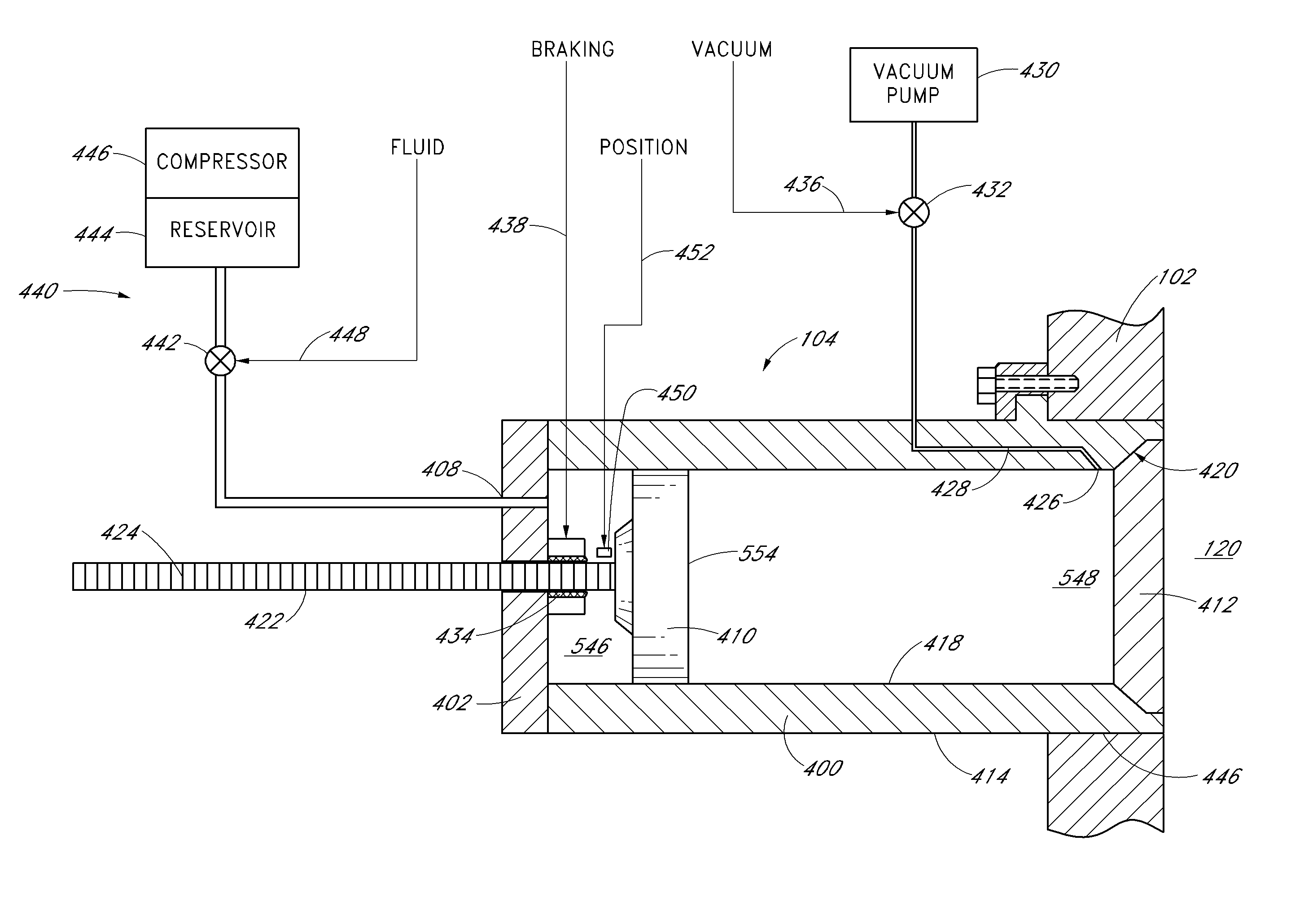
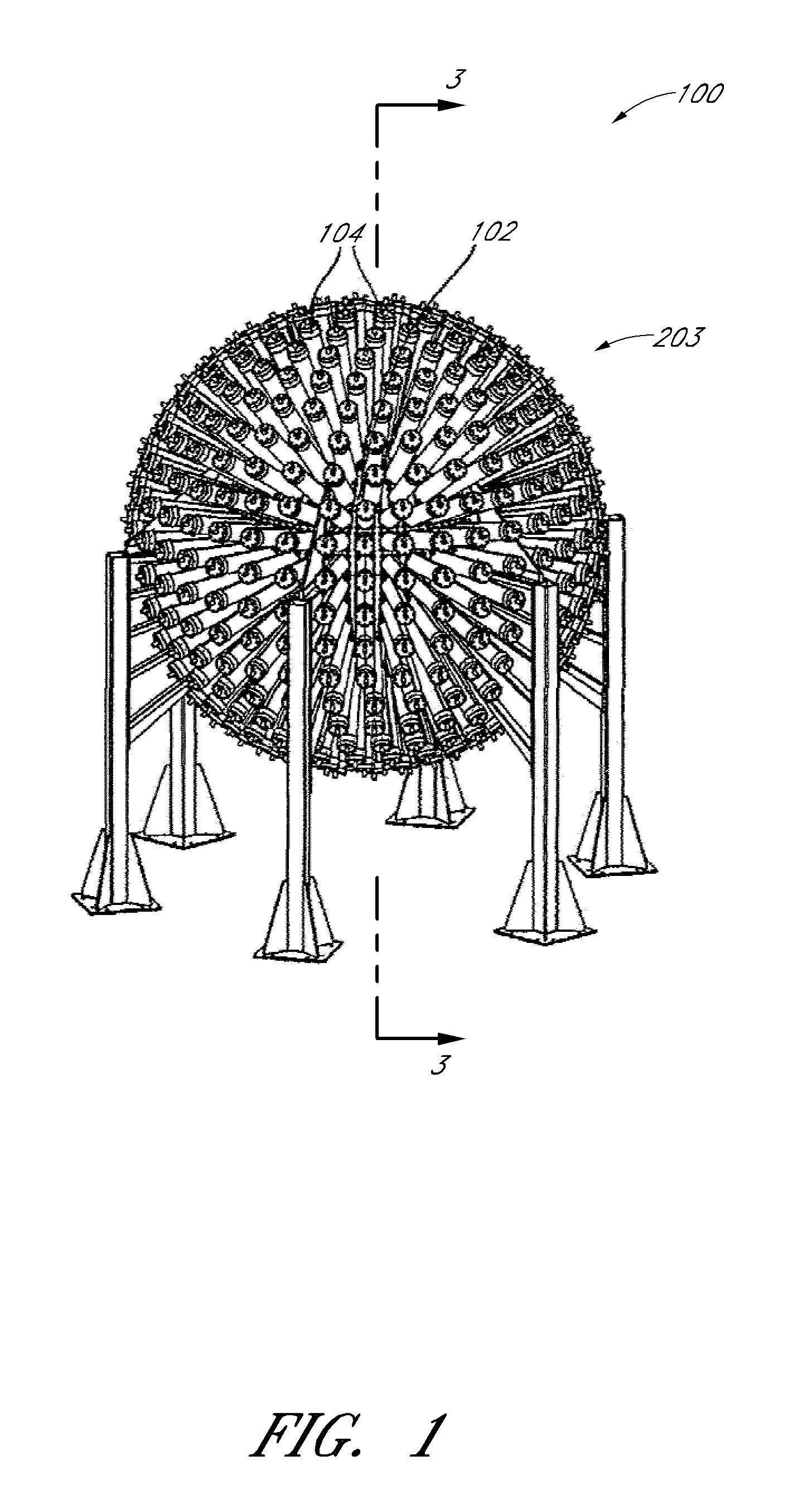
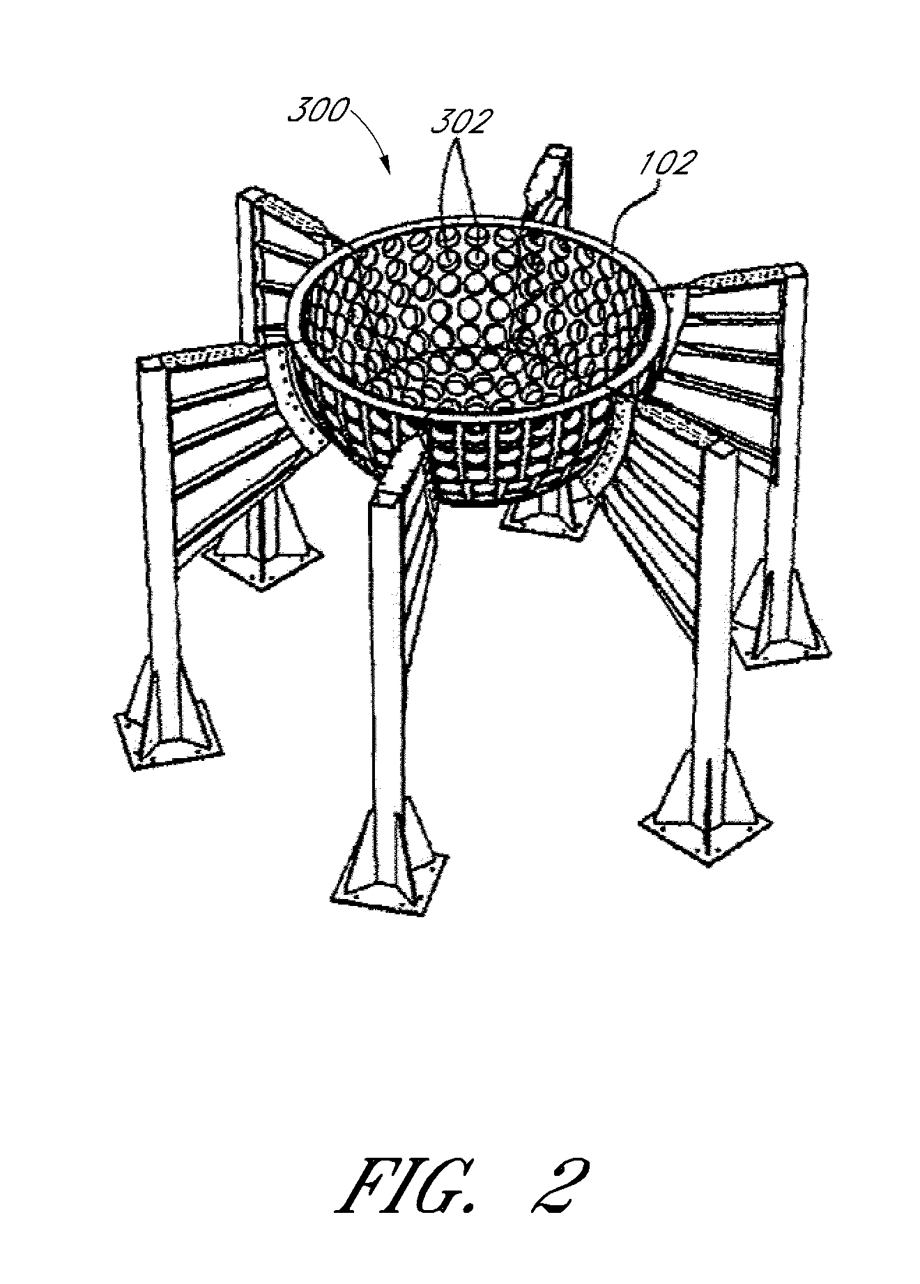
[0126]Referring to FIG. 1, a fusion reactor according to a first embodiment of the invention is shown generally at 100. The fusion reactor 100 includes a wall 102 and a plurality of radially oriented pressure wave generators 104, symmetrically arranged around an exterior of the wall. Referring to FIG. 2, in one embodiment, the wall 102 of the fusion reactor 100 may include a lower hemispherical shell 300 including a plurality of openings 302. The wall 102 of the fusion reactor 100 may also include a complimentary upper hemispherical shell shown at 203 in FIG. 1.

[0127]Referring to FIG. 3, the wall 102 of fusion reactor 100 defines an inner cavity 122 for containing a liquid medium 120. The liquid medium 120 may be a molten metal, such as lead, lithium, or sodium, or an alloy of such metals, and ma...


PUM


Abstract

An apparatus for generating a pressure wave in a medium is disclosed. The apparatus includes a plurality of pressure wave generators having respective moveable pistons, the pistons having respective control rods connected thereto. The apparatus also includes a plurality of transducers coupled to the medium and means for causing the pistons of respective ones of the plurality of the pressure wave generators to be accelerated toward respective ones of the plurality of transducers. The apparatus further includes means for causing restraining forces to be applied to respective control rods to cause respective pistons to impact respective transducers at respective desired times and with respective desired amounts of kinetic energy such that the respective desired amounts of kinetic energy are converted into a pressure wave in the medium.

Description

CROSS-REFERENCE TO RELATED APPLICATIONS[0001]This application is a continuation of U.S. patent application Ser. No. 11 / 072,963, filed Mar. 4, 2005, which is hereby incorporated by reference herein in its entirety. This application is related to U.S. patent application Ser. No. 11 / 073,276 by Laberge, filed Mar. 4, 2005, published as U.S. Patent Publication No. 2006 / 0198483, and incorporated herein by reference and to U.S. patent application Ser. No. 11 / 073,423 by Laberge filed Mar. 4, 2005, published as U.S. Patent Publication No. 2006 / 0198487, and incorporated herein by reference.BACKGROUND[0002]1. Field[0003]This invention relates to nuclear fusion reactors and more particularly to pressure wave generation in nuclear fusion reactors.[0004]2. Description of Related Art[0005]Nuclear fusion reactions involve bringing together atomic nuclei against their mutual electrostatic repulsion and fusing them together to make heavier nuclei, while at the same time releasing energy. Isotopes of ...

Claims


Application Information

Patent Timeline
Patent Type & Authority Applications(United States)
IPC IPC(8): F15C1/04
CPCG21B3/00Y02E30/18F15B21/12G10K15/043F03G7/002Y10T137/2191Y02E30/10H05H1/02
Inventor LABERGE, MICHEL GEORGESGELBART, DANIELHILL, ROSS HENRYCONNOR, DENIS J.
Owner GENERAL FUSION INC
Learn More