
Massaging Device That Is Assembled and Disassembled Easily and Quickly

a massaging device and easy-to-assemble technology, applied in the field of massaging devices, can solve problems such as difficulty for users, and achieve the effects of easy-to-replace massaging, soft massaging, and easy-to-disassembl

Inactive Publication Date: 2010-06-24
WU NA
View PDF30 Cites 79 Cited by
  • Summary
  • Abstract
  • Description
  • Claims
  • Application Information

AI Technical Summary

Benefits of technology

[0008]The primary objective of the present invention is to provide a massaging device that is assembled and disassembled easily and quickly.
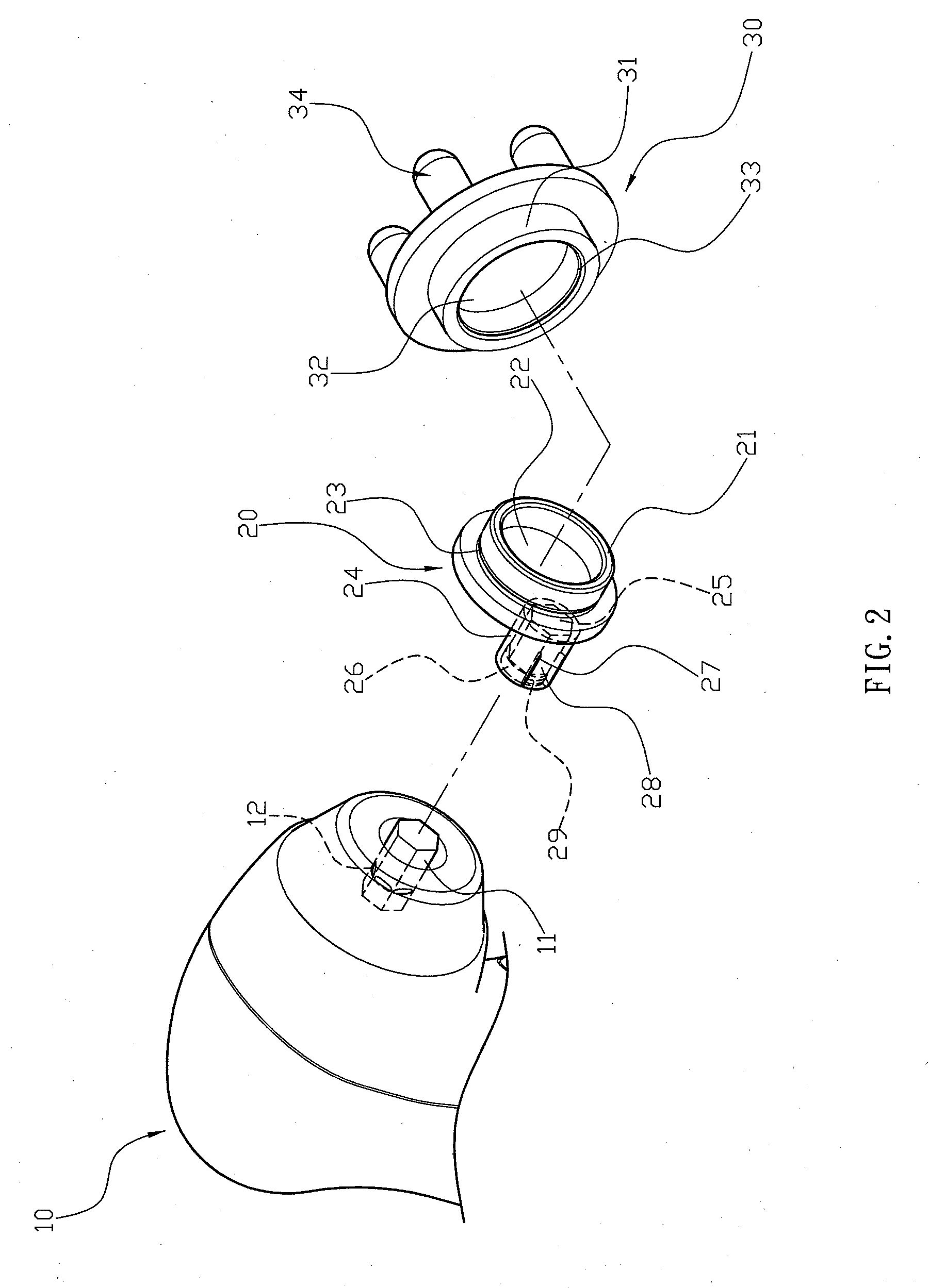
[0009]Another objective of the present invention is to provide a massaging device, wherein the retaining section of the second mounting ring is snapped onto the retaining portion of the first mounting ring to mount the second mounting ring of the massaging head onto of the first mounting ring of the rotation disk and to attach the massaging head to the rotation disk, while the locking hook of the driven member is locked onto the respective locking protrusion of the drive member to detachably lock the driven member onto the drive member and to attach the rotation disk to the support base, so that the massaging head is directly attached to the rotation disk, and the rotation disk is directly attached to the support base without needing aid of any hand tool, thereby facilitating a user assembling and disassembling the massaging device.
[0010]A further objective of the present invention is to provide a massaging device, wherein the user only needs to pull the rotation disk outwardly relative to the support base for replacement of the massaging head, thereby greatly facilitating the user replacing the massaging head 30.
[0011]A further objective of the present invention is to provide a massaging device, wherein the reaction of the eccentric rotation of the rotation disk and the massaging head is counteracted by rotation of the massaging head relative to the rotation disk, so that the massaging head is moved relative to the support base eccentrically and is moved on the user's body slowly and smoothly in a reciprocal manner to provide a softly massaging effect to the user's body and to provide a comfortable sensation to the user.

Problems solved by technology

In addition, the tightening direction of the locking screw 94 is the same as the rotation direction of the massaging head 90, so that the locking screw 94 is easily screwed and tightened to an excessive extent during rotation of the massaging head 90, thereby causing difficulty to the user when the user wishes to unscrew the locking screw 94.

Method used


Image

  • Massaging Device That Is Assembled and Disassembled Easily and Quickly
  • Massaging Device That Is Assembled and Disassembled Easily and Quickly
  • Massaging Device That Is Assembled and Disassembled Easily and Quickly

Examples


Embodiment Construction

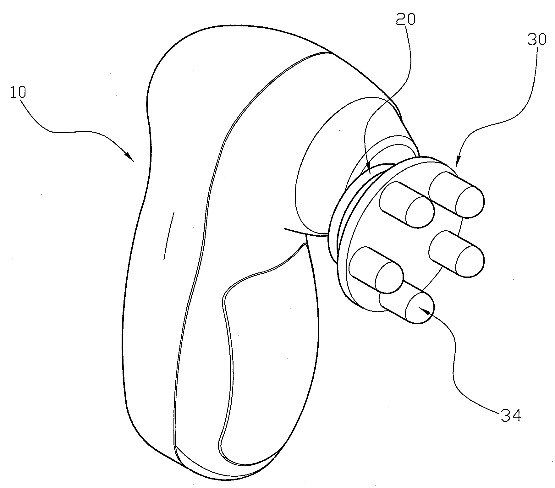
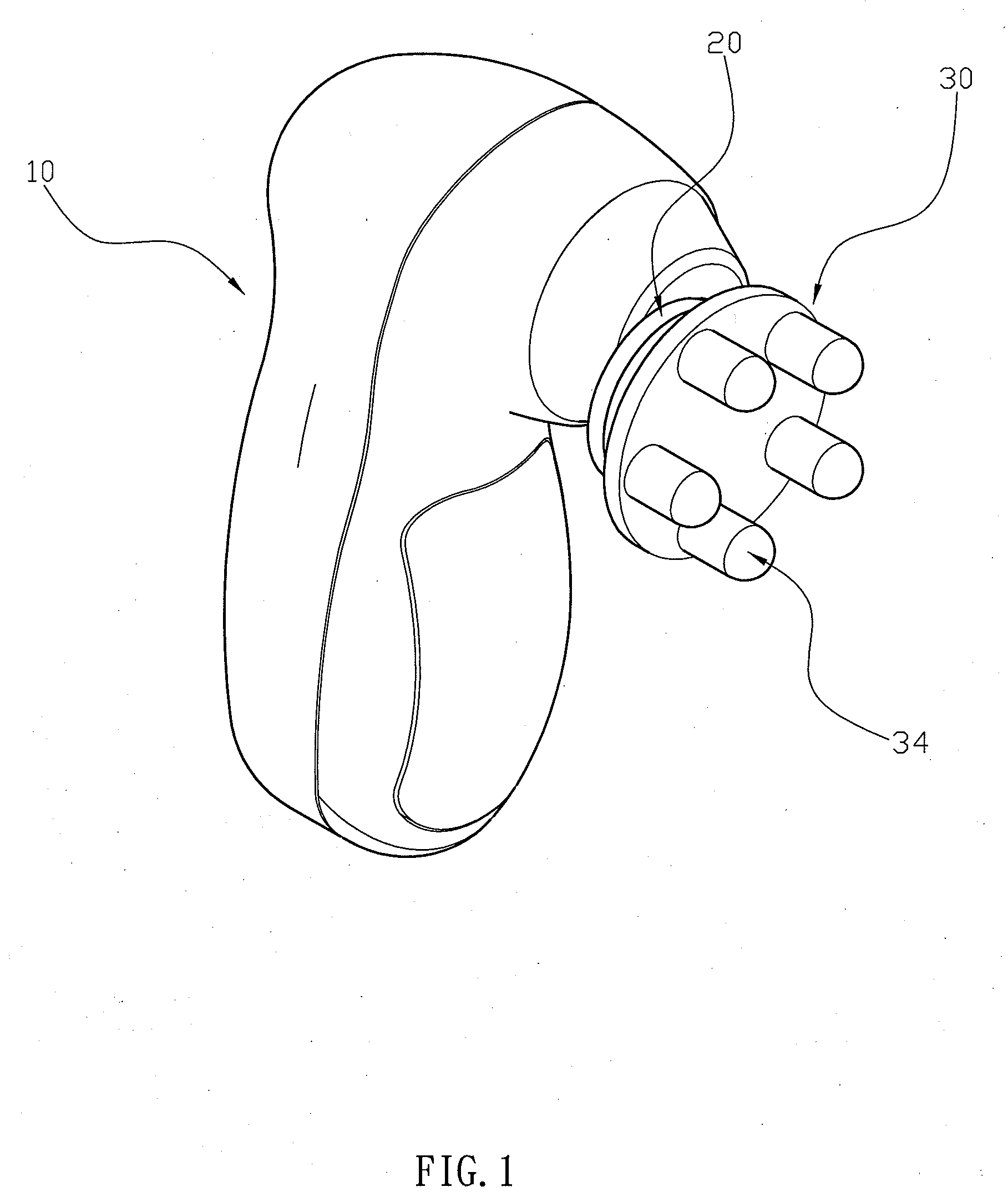
[0027]Referring to the drawings and initially to FIGS. 1-5, a massaging device in accordance with the preferred embodiment of the present invention comprises a support base 10, a drive member 11 rotatably mounted on the support base 10, a rotation disk 20 rotatable relative to the support base 10 and provided with a driven member 24 which is detachably mounted on and rotated by the drive member 11 to drive the rotation disk 20 to rotate relative to the support base 10, and a massaging head 30 mounted on the rotation disk 20 to rotate in concert with the rotation disk 20 and rotatable relative to the rotation disk 20.

[0028]The support base 10 has an inner portion provided with a drive motor (not shown) connected with the drive member 11 to drive and rotate the drive member 11.

[0029]The drive member 11 has a periphery provided with a plurality of locking protrusions 12. Each of the locking protrusions 12 of the drive member 11 is perpendicular to a longitudinal direction of the drive ...


PUM


Abstract

A massaging device includes a support base, a drive member rotatably mounted on the support base, a rotation disk rotatable relative to the support base and provided with a driven member which is detachably mounted on and rotated by the drive member to drive the rotation disk to rotate relative to the support base, and a massaging head mounted on the rotation disk to rotate in concert with the rotation disk and rotatable relative to the rotation disk. Thus, the massaging head is directly attached to the rotation disk, and the rotation disk is directly attached to the support base without needing aid of any hand tool.

Description

BACKGROUND OF THE INVENTION[0001]1. Field of the Invention[0002]The present invention relates to a massaging device and, more particularly, to a portable massaging device whose massaging head is operated in an eccentrically revolving manner.[0003]2. Description of the Related Art[0004]A conventional massaging device in accordance with the prior art shown in FIGS. 13 and 14 comprises a support base 60, a drive member 61 rotatably mounted on the support base 60, a substantially Z-shaped crank 70 having a first end provided with an input rod 72 secured on and rotated by the drive member 61 and a second end provided with an output rod 73 which is parallel with the input rod 72 and is provided with a screw bore 71, a massaging head 90 mounted on the output rod 73 of the crank 70 to rotate with the output rod 73 of the crank 70 and having a central portion provided with a stepped through hole 93, a bearing 80 mounted between the output rod 73 of the crank 70 and the massaging head 90, and...

Claims


Application Information

Patent Timeline
IPC IPC(8): A61H7/00A61H15/00
CPCA61H2201/1685A61H7/004
Inventor WU, DONG-HER
Owner WU NA
Learn More