
Method and system to perform optical moving object detection and tracking over a wide area

a technology of optical moving object detection and tracking over a wide area, applied in the field of reconnaissance and surveillance systems, can solve problems such as inacceptable levels of false alarms of conventional moving object detection algorithms

Active Publication Date: 2010-06-24
STATE OF ISRAEL MINIST OF AGRI & RURAL DEV AGRI RES ORG (A R O) (VOLCANI CENT)
View PDF12 Cites 52 Cited by
  • Summary
  • Abstract
  • Description
  • Claims
  • Application Information

AI Technical Summary

Benefits of technology

The patent describes a method and system for detecting and tracking moving objects in real-time over wide areas of coverage using images captured by a camera on an aircraft or other airborne vehicle. The system combines motion detection and velocity estimation techniques to extract and track objects in multi-exposures, which are images taken at different times but overlapping in the same area. The system can detect small objects in wide areas with high accuracy and reliability, even in the presence of environmental conditions that may cause false alarms. The system can be used for surveillance, law enforcement, and other applications where real-time object detection and tracking are necessary.

Problems solved by technology

Such differences generally result in unacceptable levels of false alarms by conventional moving object detection algorithms.

Method used


Image

  • Method and system to perform optical moving object detection and tracking over a wide area
  • Method and system to perform optical moving object detection and tracking over a wide area
  • Method and system to perform optical moving object detection and tracking over a wide area

Examples


Embodiment Construction

[0025]Embodiments of the subject invention concern methods and systems for automated real-time moving object detection and tracking over very wide areas using non-static cameras.

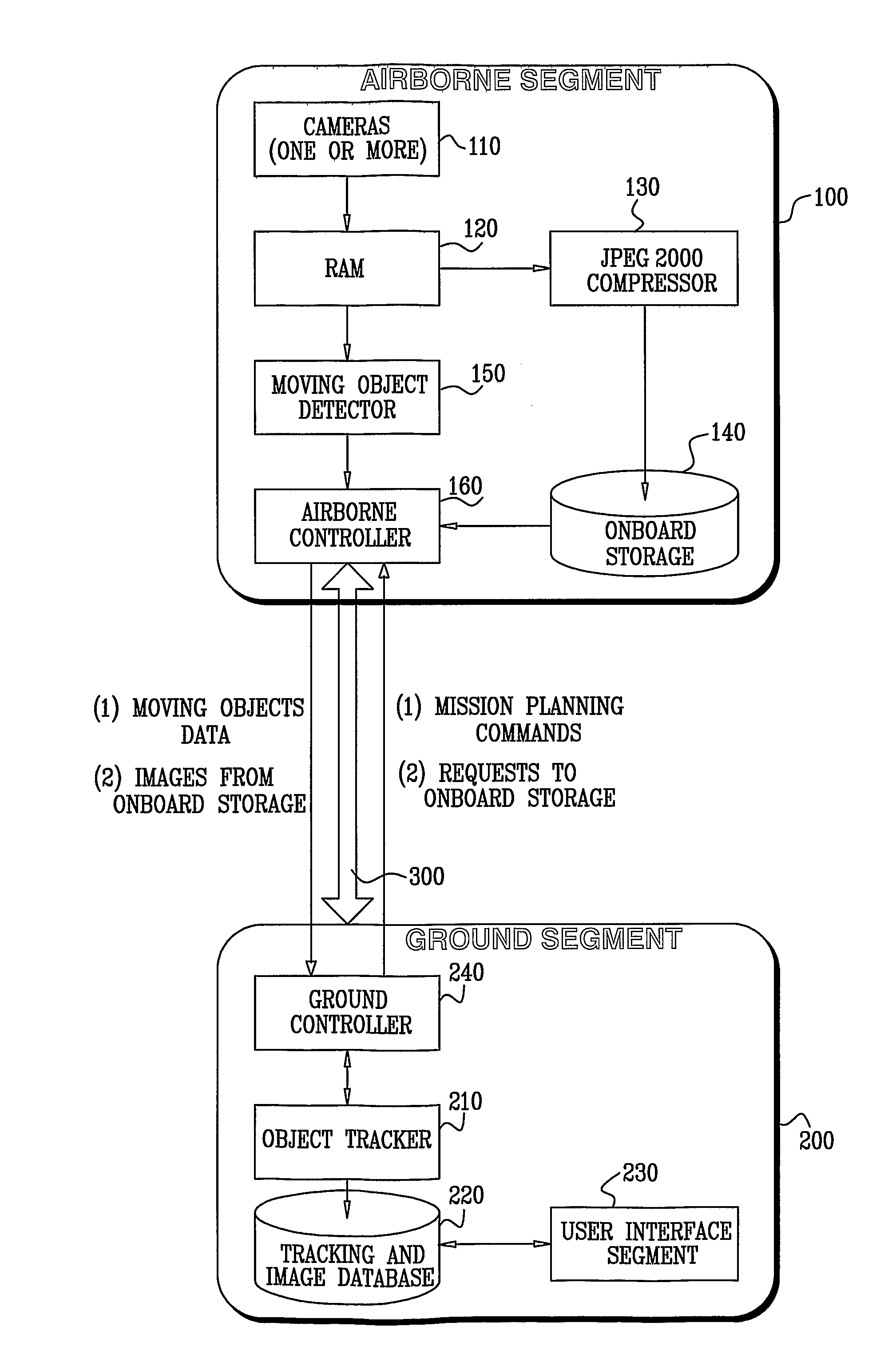
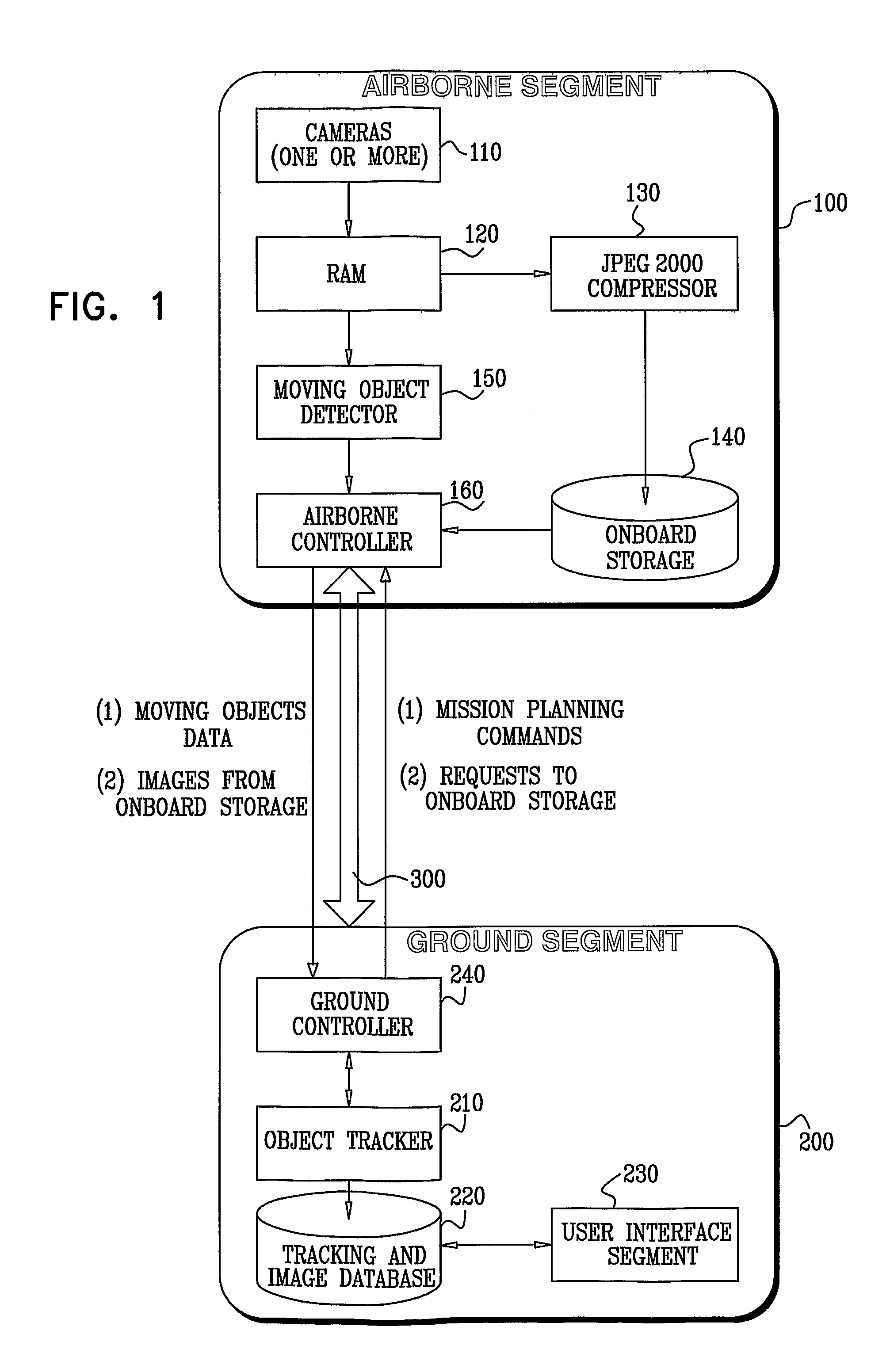
[0026]Reference is now made to FIG. 1, which is a simplified block diagram of a system for moving object detection and tracking over a wide area, in accordance with an embodiment of the present invention. Shown in FIG. 1 is an airborne segment 100, which is operative on board an aerial platform to capture images, to process the captured images to detect moving objects, and to generate moving object data. Counterpart to the airborne unit is a ground segment 200, which is operative at a ground station to issue mission commands and requests to airborne unit 100, to process moving object data generated by airborne segment 100, and track the moving objects.

[0027]Airborne segment 100 includes one or more cameras 110, and RAM memory 120 for temporarily storing raw image data, an optional JPEG2000 compressor 130 for...


PUM


Abstract

A method for moving object detection, comprising generating a time series of multi-exposures of scenes, each multi-exposure of a scene comprising a sequence of at least two at least partially overlapping images of that scene captured in rapid succession, wherein the time series of multi-exposures periodically revisits substantially the same scenes, detecting moving objects within each multi-exposure by comparing its sequence of overlapping images, and tracking objects by comparing moving objects detected within multi-exposures of substantially the same scenes.

Description

PRIORITY REFERENCE TO RELATED APPLICATIONS[0001]This application claims benefit of U.S. Provisional Application No. 60 / 954,366, entitled METHOD AND SYSTEM TO PERFORM OPTICAL MOVING TARGET AND CHANGE DETECTION INDICATION, filed on Aug. 7, 2007 by inventor Michael Pechatnikov. This application is a continuation-in-part of pending U.S. application Ser. No. 11 / 607,511 entitled DIGITAL MAPPING SYSTEM BASED ON CONTINUOUS SCANNING LINE OF SIGHT, filed on Nov. 30, 2006.FIELD OF THE INVENTION[0002]The field of the subject invention is reconnaissance and surveillance systems. More specifically, the subject invention relates to wide area persistent monitoring systems.BACKGROUND OF THE INVENTION[0003]Moving object detection and change detection is a well-researched field, with many applications in the security and surveillance domain. Moving object and change detection systems are required to provide automated, robust and real-time detection of moving objects with a high probability of success ...

Claims


Application Information

Patent Timeline
Patent Type & Authority Applications(United States)
IPC IPC(8): G06K9/00H04N7/18
CPCG06T7/20G06T2207/30232G06T2207/30181G06T7/2053G06T7/254
Inventor PECHATNIKOV, MICHAEL
Owner STATE OF ISRAEL MINIST OF AGRI & RURAL DEV AGRI RES ORG (A R O) (VOLCANI CENT)
Learn More