
Exhaust gas recirculating device for internal combustion engines

a technology of exhaust gas recirculating device and internal combustion engine, which is applied in the direction of machines/engines, mechanical equipment, and non-fuel substance addition to fuel, etc., can solve the problems of clogging the distribution passage outlet of egr gas

Active Publication Date: 2010-06-24
HONDA MOTOR CO LTD
View PDF9 Cites 15 Cited by
  • Summary
  • Abstract
  • Description
  • Claims
  • Application Information

AI Technical Summary

Benefits of technology

The present invention provides an exhaust gas recirculating device for internal combustion engines that can prevent clogging of the EGR gas introduction port even when there is backflow of intake from the engine main body. This is achieved by designing the EGR gas introduction port with an inlet end and an outlet end, and an increasing cross-sectional area from the inlet end to the outlet end. The EGR gas introduction port can be easily formed by drilling or the like, and it is convenient and economical to form the passages for EGR gas and blow-by gas in a way that prevents clogging. The EGR gas introduction port can be positioned adjacent to the interface between the EGR passage member and the intake pipe, and it can be formed without requiring any additional components. The engine can have a plurality of cylinders, and the EGR passage member can include a plurality of intake passages corresponding to the different cylinders of the engine. The EGR gas can be distributed evenly to the different intake passages, and this also contributes to the prevention of clogging. The EGR chamber enables the exhaust gas to be distributed evenly to the different intake passages, and this also contributes to the prevention of clogging. The blow-by gas can be distributed evenly to the different cylinders of the engine, and this also contributes to the prevention of clogging.

Problems solved by technology

However, according to the proposal disclosed in Patent Document 1, because the distribution passage outlet for EGR gas is provided adjacent to the main part of the intake flow, when such a backflow occurs, carbon particles and oil contained in the blow-by gas may be deposited on an area surrounding the distribution passage outlet for EGR gas, and this could cause a clogging of the distribution passage outlet for EGR gas.

Method used


Image

  • Exhaust gas recirculating device for internal combustion engines
  • Exhaust gas recirculating device for internal combustion engines
  • Exhaust gas recirculating device for internal combustion engines

Examples


Embodiment Construction

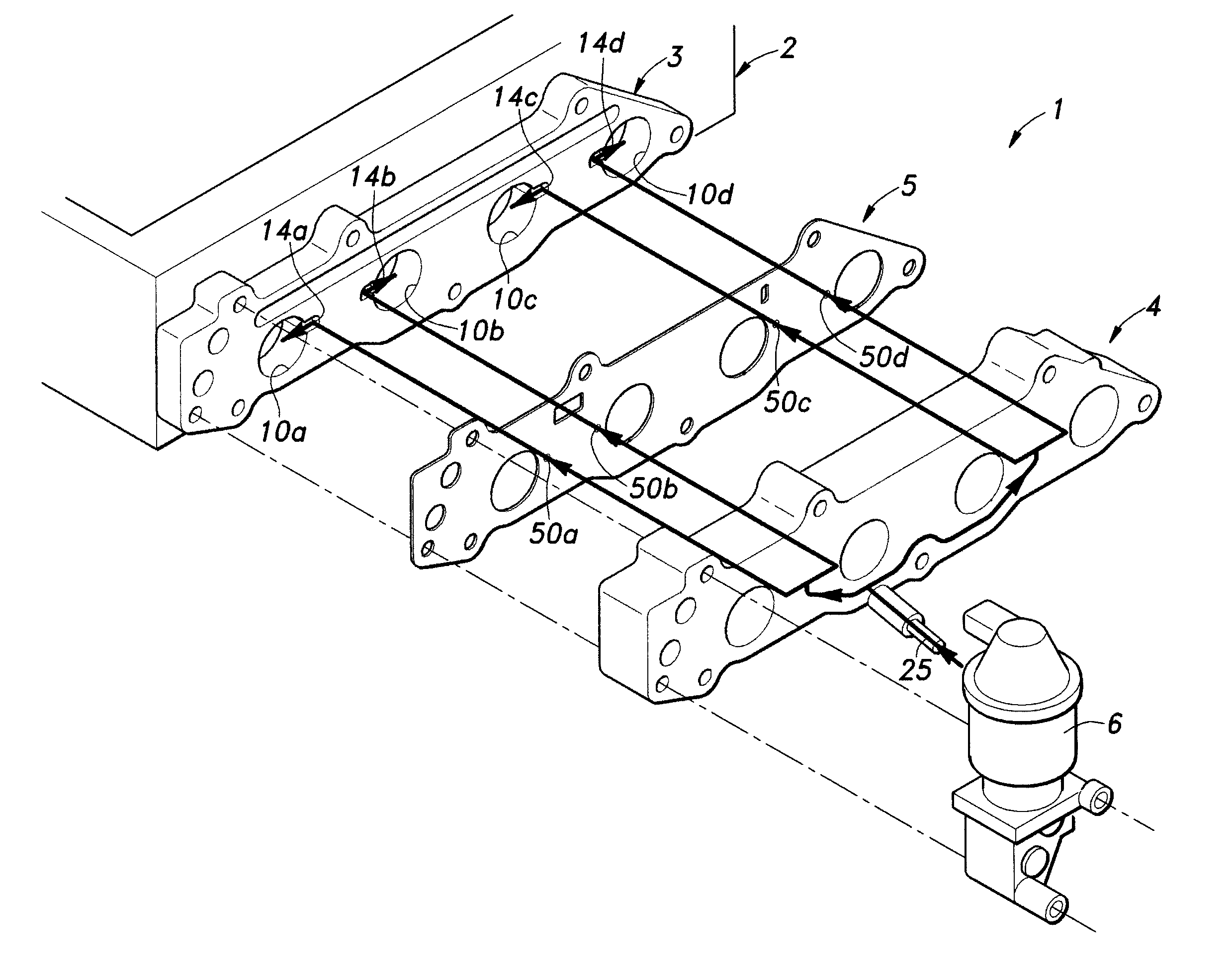
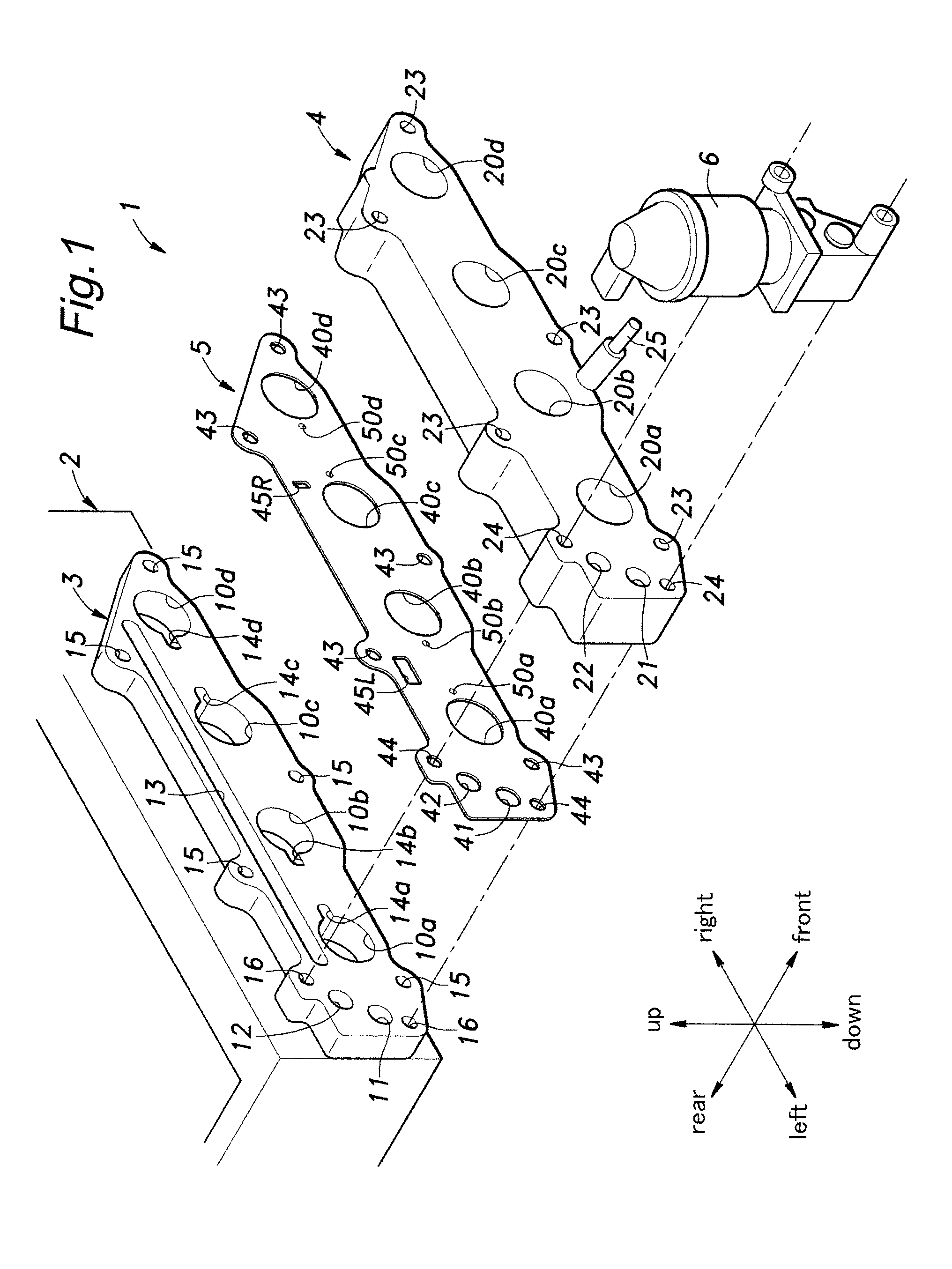
[0030]In the following description, for the convenience of description, orientations of various parts are indicated by the notation defined in FIG. 1 although the actual orientation of the various parts may vary depending on the actual orientation of the engine. Also, the engine of the illustrated embodiment consists of a four-cylinder engine, and corresponding components of different cylinder are denoted by adding a suffix a-b. For instance, an intake port is generally denoted with numeral 10, and an intake port of any particular cylinder is denoted with numeral 10a-10d. However, the present invention is not limited by this particular example, but may be applicable to engines of different types, such as single cylinder engines, in-line multiple cylinder engines and V-type multiple cylinder engines.

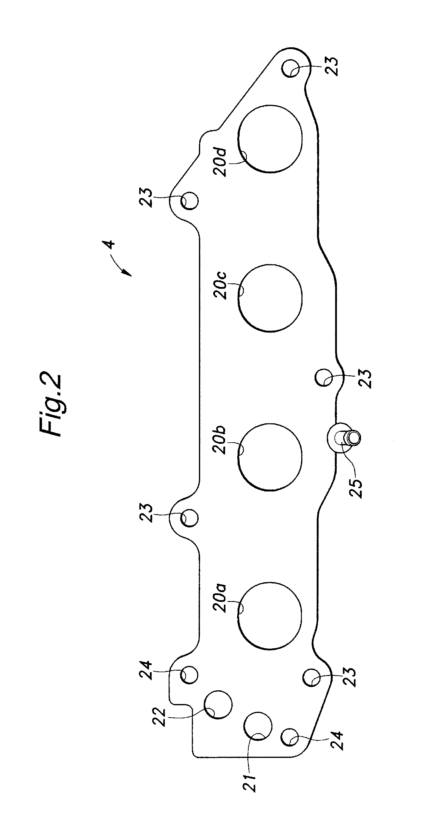
[0031]FIG. 1 is an overall exploded perspective view of an EGR device embodying the present invention, and FIGS. 2-4 show an EGR plate 4 of the EGR device. FIGS. 5 and 6 show a gasket 5 o...


PUM


Abstract

In an exhaust gas recirculating device for an internal combustion engine, an EGR gas introduction port (32) for feeding EGR gas to an intake passage (20) includes an inlet end and an outlet end, and has a cross sectional area progressively increasing from the inlet end to the outlet end, the outlet end (49) opening out at an upper part of the intake passage. Because the EGR gas introduction port has a cross sectional area progressively increasing from the inlet end to the outlet end thereof, and the outlet end of the EGR gas introduction port opens out at an upper part of the intake passage, even when an intake flow is blown back from the engine main body, carbon and oil that may be contained in the EGR gas can be prevented from being deposited in the EGR gas introduction port, and this prevents the clogging of the EGR gas introduction port.

Description

TECHNICAL FIELD[0001]The present invention relates to a device for recirculating a part of exhaust gas of an internal combustion engine to an intake system thereof.BACKGROUND OF THE INVENTION[0002]Current internal combustion engines such as automotive internal combustion engines typically comprise an exhaust gas recirculating device (which is referred to as EGR device hereinafter) that recirculates a part of exhaust gas (which is referred to as exhaust gas recirculating gas or EGR gas hereinafter) to the intake system thereof for the purposes of improving fuel economy and reducing the NOx contents in the exhaust gas.[0003]For such EGR devices, proposals have been made to prevent the clogging of an introduction port for introducing EGR gas into an intake passage. According to a proposal disclosed in Patent Document 1 (Japanese patent laid open publication No. 2008-75522), a distribution passage for EGR gas and blow-by gas is formed in a plate member provided between an intake manifol...

Claims


Application Information

Patent Timeline
Patent Type & Authority Applications(United States)
IPC IPC(8): F02M25/07
CPCF02M13/00F02M25/06Y02T10/121F02M25/0773F02M25/0747F02M26/41F02M26/54Y02T10/12
Inventor TAIRA, TAKAHIRO
Owner HONDA MOTOR CO LTD
Learn More