
Fiber optic multi dwelling unit deployment appartus and methods for using the same

a fiber optic multi-dwelling unit and fiber optic technology, applied in the direction of fiber mechanical structures, instruments, constructions, etc., can solve the problems of overflowing the capacity of the pathway, requiring risky and laborious cutting procedures to open the cable, and difficult management, so as to reduce the width and reduce the width

Inactive Publication Date: 2010-06-17
COMMSCOPE TECH LLC
View PDF9 Cites 39 Cited by
  • Summary
  • Abstract
  • Description
  • Claims
  • Application Information

AI Technical Summary

Benefits of technology

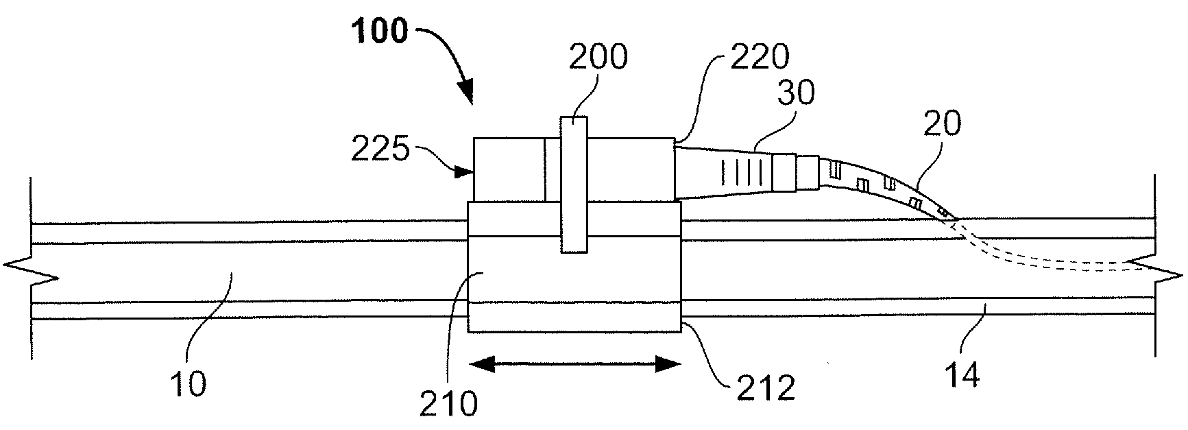
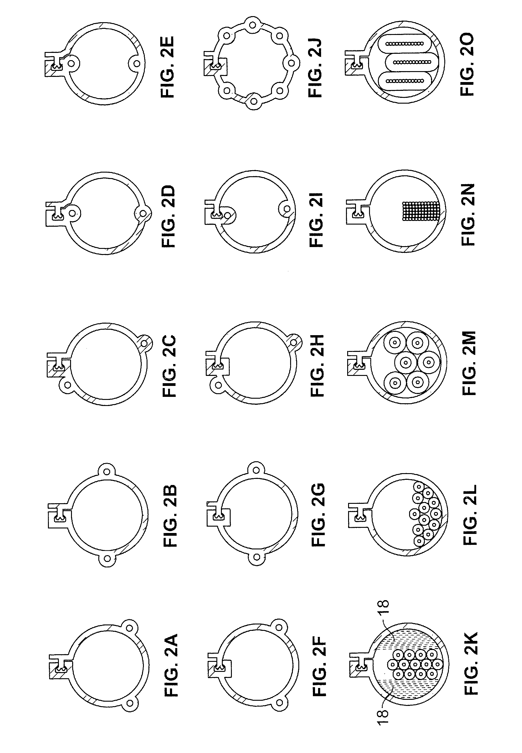
The present invention relates to an optical fiber terminal apparatus that includes an optical fiber protection jacket with a seam that can be opened at a selected location along the jacket. The apparatus also includes an adapter terminal that can be mated with the optical fiber protection jacket. The seam can be selectively closed with a snap. The optical fiber protection jacket can have a longitudinally slidable adapter terminal that can be snapped onto the jacket. The adapter terminal includes a body portion that supports a coupling between the optical fiber and a customer optical fiber. The optical fiber protection jacket can have a pre-defined bend direction and can limit bend direction. The apparatus also includes a protective cover and a dust cap for the optical fiber protection jacket. The invention allows for easy and secure connection of optical fibers in a low-profile manner.

Problems solved by technology

Upgrading existing structures from a copper network to a fiber optic network poses issues regarding suitable and acceptable pathways required to deliver optical fiber cabling compared to conventional single dwelling homes that typically route the fiber directly via aerial or buried cables.
These cables can quickly overwhelm the capacity of the pathway and in turn be difficult to manage (e.g., tangling of drop cables or the like).
Single sheath methods, while they may address the congestion issue, generally require risky and labor intensive cutting procedures to open the cable.

Method used


Image

  • Fiber optic multi dwelling unit deployment appartus and methods for using the same
  • Fiber optic multi dwelling unit deployment appartus and methods for using the same
  • Fiber optic multi dwelling unit deployment appartus and methods for using the same

Examples


Embodiment Construction

[0045]The present invention now will be described more fully hereinafter with reference to the accompanying drawings, in which illustrative embodiments of the invention are shown. In the drawings, the relative sizes of regions or features may be exaggerated for clarity. This invention may, however, be embodied in many different forms and should not be construed as limited to the embodiments set forth herein; rather, these embodiments are provided so that this disclosure will be thorough and complete, and will fully convey the scope of the invention to those skilled in the art.

[0046]It will be understood that, although the terms first, second, etc. may be used herein to describe various elements, components, regions, layers and / or sections, these elements, components, regions, layers and / or sections should not be limited by these terms. These terms are only used to distinguish one element, component, region, layer or section from another region, layer or section. Thus, a first elemen...


PUM


Abstract

An optical fiber terminal apparatus includes an optical fiber protection jacket including a pre-defined, longitudinally extending seam that can be opened at a selected location along the jacket to define an opening into the optical fiber protection jacket at the selected location. The apparatus further includes an adapter terminal configured to mate with an outer profile of the optical fiber protection jacket. The adapter terminal includes a body portion that is configured to support a coupling between an optical fiber extending from the opening in the optical fiber protection jacket to a customer optical fiber. The seam may be repeatably and selectively closable.

Description

RELATED APPLICATIONS[0001]The present application claims the benefit of and priority from U.S. Provisional Application No. 61 / 121,751 (Attorney Docket No. TO-00266- US / 5487-290PR), filed Dec. 11, 2008, the disclosure of which is hereby incorporated herein in its entirety by reference.BACKGROUND OF THE INVENTION[0002]The present invention relates to optical fiber products and, more particularly, to optical fiber deployment products and methods for using the same.[0003]Optical fiber networks (e.g. Plastic, Glass, Multimode, Singlemode, etc.) are increasingly being installed to support high speed voice and data communications. As part of this effort, the optical fiber deployment is being expanded out from the central office of the communication service provider companies, such as Regional Bell Operating Companies (RBOCs), to the subscriber locations, such as apartments or condominiums. Such subscriber locations are commonly referred to as multi-dwelling units (MDUs), where conventional...

Claims


Application Information

Patent Timeline
Patent Type & Authority Applications(United States)
IPC IPC(8): G02B6/36G02B6/44G02B6/00E04B1/00
CPCG02B6/4475G02B6/4466G02B6/3825G02B6/475G02B6/4431G02B6/4401G02B6/3851G02B6/4402G02B6/4403G02B6/4404G02B6/4405G02B6/4407G02B6/4486
Inventor ALLEN, BARRY WAYNEBRAGA, DAVID J.
Owner COMMSCOPE TECH LLC
Learn More