
Method and apparatus for measuring electric currents

a technology of electric current and measuring device, which is applied in the direction of magnetic field magnitude/direction, measurement device, instruments, etc., can solve the problems of significant reduction of sensitivity, and achieve the effect of avoiding the reduction of measuring accuracy by stray fields and simple assembly and disassembly

Inactive Publication Date: 2010-06-17
ESW
View PDF5 Cites 3 Cited by
  • Summary
  • Abstract
  • Description
  • Claims
  • Application Information

AI Technical Summary

Benefits of technology

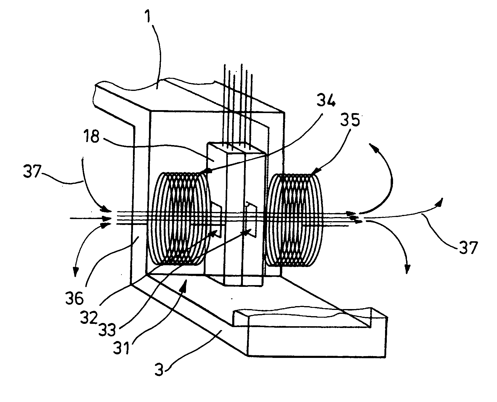
[0011]As a result of the superimposition of the field components in the same direction it is especially possible to omit a core of a ferromagnetic material which would bundle the field to be measured. This has the significant advantage that the sensor is not subject to saturation effects. Such saturation can be created, for example, if in connection with converters a final power stage is operated in short circuit. Also, by avoiding saturation effects, self-heating of the sensor is avoided. A sensor temperature which would limit the capability of operation of the sensor by exceeding a maximum permissible operational temperature, would therefore be determined essentially only by the prevailing ambient conditions and not by a negative output in the area of the sensor. Such a negative output can be caused, for example, by magnetic reversal loses.
[0017]The functional security can be increased by carrying out at least one sensor test.
[0020]Decreases of the measuring accuracy by stray fields can be avoided by carrying out an electromagnetic screening in the area of the sensor. This is particularly useful when there are interference fields or adjacent conductors.
[0021]A particularly simple assembly and disassembly is achieved by securing a sensor housing which positions the sensor with respect to space by using at least one cable binder. Also possible are the use of screws or clamps or glued connections.

Problems solved by technology

Consequently, there is in particular no compensation of field components which would be generated if the current were conducted in the same direction past oppositely located sides of the sensor and which would lead to a significant reduction of the sensitivity.

Method used


Image

  • Method and apparatus for measuring electric currents
  • Method and apparatus for measuring electric currents
  • Method and apparatus for measuring electric currents

Examples


Embodiment Construction

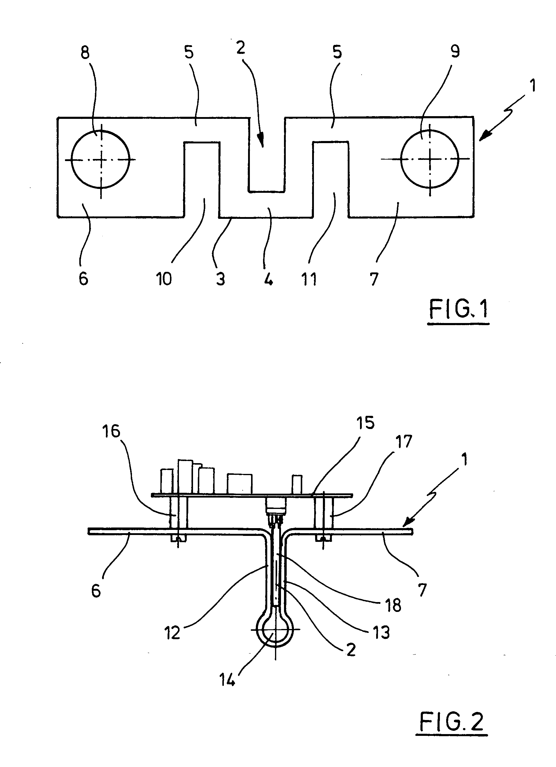
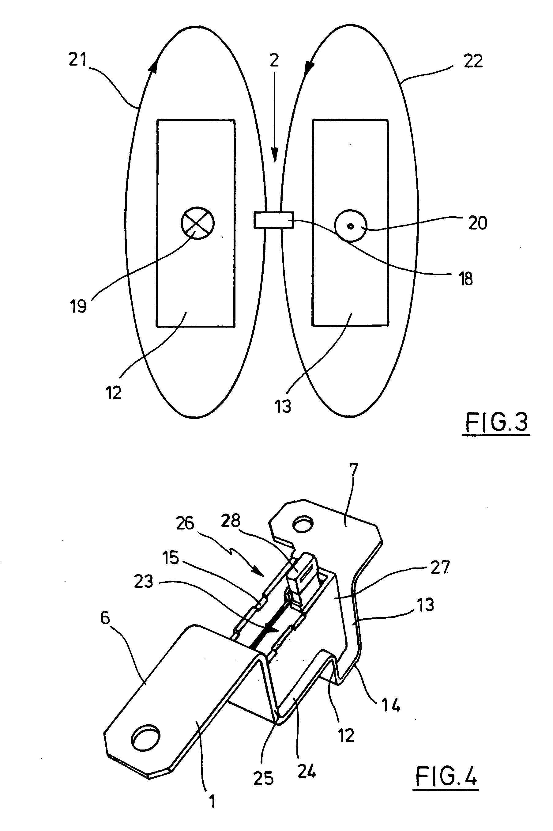
[0032]FIG. 1 is a side view of a current rail 1 which is provided in the area of a sensor pick-up 2 with a U-shaped conductor configuration 3. The ends of the conductor configuration 3 facing away from the basic leg 4 are typically connected through transverse webs 5 to main areas 6, 7 of the current rail 1. The main areas 6, 7 typically have recesses 8, 9 for fastening the current rail 1 in the area of counter elements, not shown. Side legs of the U-shaped conductor configuration 3 are separated from the principal areas 6, 7 by incisions 10, 11 in such a way that a connection is realized only from the transverse webs 5. In the case of such current rails 1 the sensor receiving space 3 and the incisions 10, 11 can be produced, for example, in the case of greater material thicknesses by milling cutting or in the case of smaller material thicknesses by bending in the area of the current rail 1. In the case of longer current rails 1, typically the transverse webs 5 are made correspondin...


PUM


Abstract

A method and an apparatus for measuring electric currents include at least one sensor for measuring the magnitude of the field strength depending on the current. The current to be measured is conducted past the sensor at least partially with oppositely directed directional components at the sensor. At least one magnetic field sensor can be used as a sensor.

Description

BACKGROUND OF THE INVENTION[0001]1. Field of the Invention[0002]The present invention relates to a method of measuring electric currents, wherein a magnetic field strength is measured which depends on the magnitude of the current being measured by using at least one sensor.[0003]The present invention also relates to an apparatus for measuring electric currents which includes at least one sensor for determining a magnetic field strength which depends on the magnitude of the current.[0004]2. Description of the Related Art[0005]Methods and apparatus of the above-described type are known already in the art in the form of different embodiments. In particular, in a galvanically separate current measurement in the range of high currents, typically with values of several 100 Ampere, in the past it has not been possible to meet all requirements with respect to high sensitivity and susceptibility to trouble, while simultaneously being of compact to the construction. A typical field of applica...

Claims


Application Information

Patent Timeline
Patent Type & Authority Applications(United States)
IPC IPC(8): G01R33/02
CPCG01R1/24G01R15/207G01R15/146G01R35/00G01R31/2829
Inventor WENSKE, JANSCHEFFEL, JURGENKOBISCH, ULF
Owner ESW
Learn More