
Wireless sensor node

a sensor node and wireless communication technology, applied in data switching networks, instruments, coding, etc., can solve the problems of high power consumption, low power consumption and low price, and difficult to implement a small-sized sensor node device. , to achieve the effect of reducing power consumption

Inactive Publication Date: 2010-06-10
ELECTRONICS & TELECOMM RES INST
View PDF10 Cites 10 Cited by
  • Summary
  • Abstract
  • Description
  • Claims
  • Application Information

AI Technical Summary

Benefits of technology

[0009]The present invention provides a low-priced, small-sized and low-powered wireless sensor node which combines functional modules to perform specific functions without an extra processor to control a device. Furthermore, the present invention provides a wireless sensor node which minimizes power consumption by independently driving individual functional modules. In addition, the present invention provides a wireless sensor node which is operated under control of a remote control node without any processor and operating software.
[0010]The present invention provides a low-priced, small-sized and low-powered wireless sensor node which operates functional modules to cooperatively perform its individual functions without an extra processor to control operation of a device. Further, the present invention provides a wireless sensor node which minimizes power consumption by independently driving functional modules. In addition, the present invention provides a wireless sensor node which is independently operated under control of a remote control node with no processor and operating software.

Problems solved by technology

In this case, however, it is difficult to implement an existing sensor node employing both the MCU and the wireless communication module that features small size, low power consumption and low price.
That is because the existing sensor node has power supplied to all of its modules even when some of the modules are needed to perform its functions, which leads to a high power consumption.
Hence, since the MCU and memory need to be incorporated in the sensor node device, it is difficult to implement a low-priced, small-sized sensor node device.

Method used


Image

  • Wireless sensor node
  • Wireless sensor node
  • Wireless sensor node

Examples


Embodiment Construction

[0024]The following detailed description is provided to assist the reader in gaining a comprehensive understanding of the methods, apparatuses and / or systems described herein. Various changes, modifications, and equivalents of the systems, apparatuses and / or methods described herein will suggest themselves to those of ordinary skill in the art. Descriptions of well-known functions and structures are omitted to enhance clarity and conciseness.

[0025]An exemplary wireless sensor node has been designed to be divided into functional modules on a function basis and to operate the functional modules to cooperatively perform its individual functions.

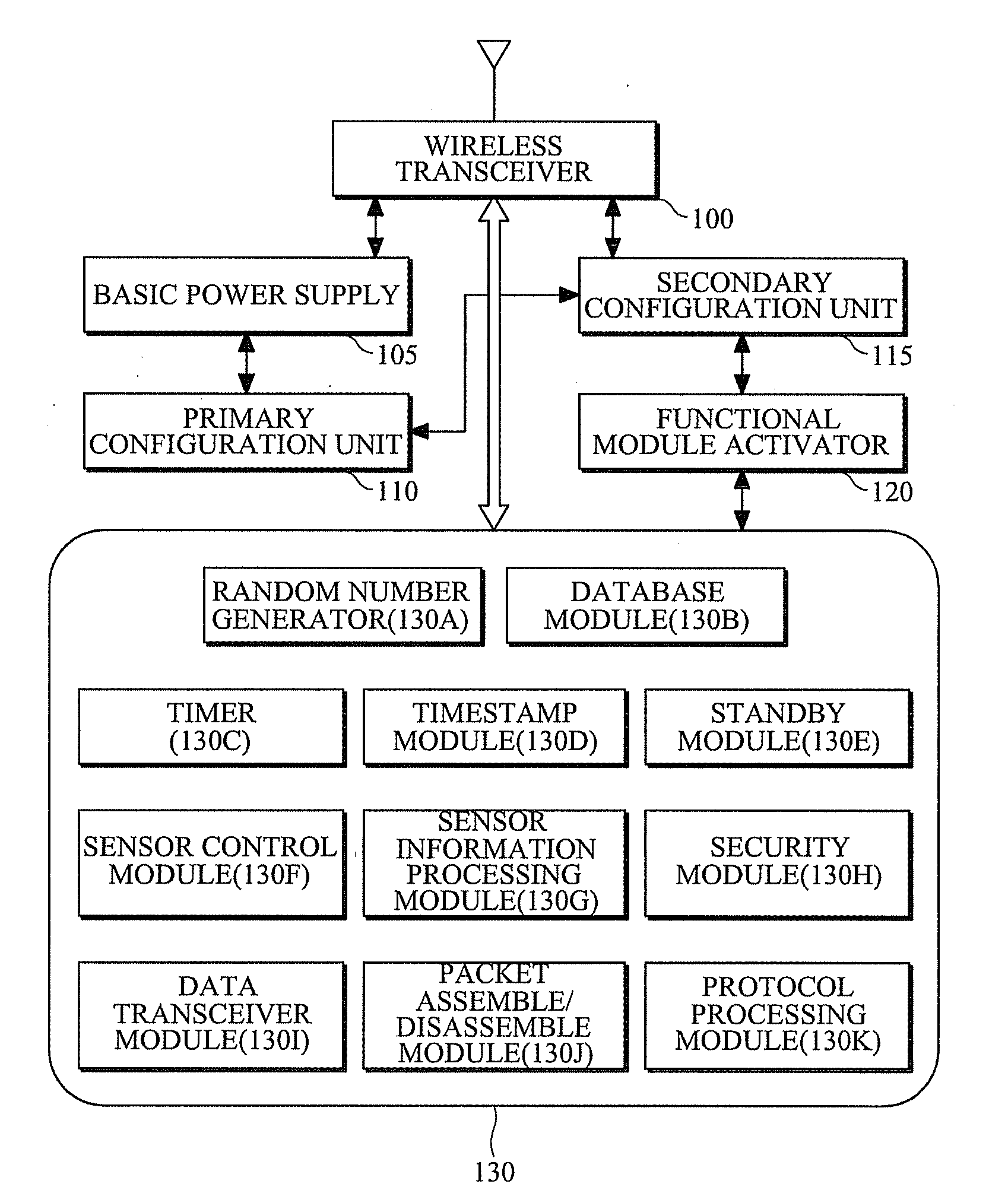
[0026]FIG. 1 is a block diagram illustrating a wireless sensor node according to an exemplary embodiment of the present invention.

[0027]The wireless sensor node includes a wireless transceiver 100, a primary configuration unit 110, a secondary configuration unit 115, a basic power supply 105, functional modules 130, and a functional module activ...


PUM


Abstract

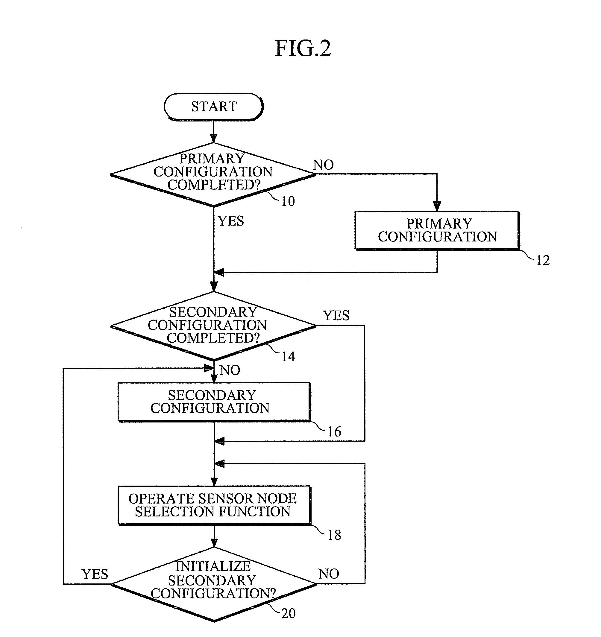
A wireless sensor node is provided which is divided into functional modules on a function basis and operates the functional modules to cooperatively perform its individual functions. The wireless sensor node includes a wireless transceiver to wirelessly communicate with a control node; a primary configuration unit to set a node identification address in communication with a control node; a secondary configuration unit to use the node identification address to register with the control node and set an address for communication which is assigned by the control node; a basic power supply to supply power to modules for communication and sensor control; functional modules to perform data processing and sensor control; and a functional module activator to activate the functional modules according to a type of received data or an operation for data transmission.

Description

CROSS REFERENCE TO RELATED APPLICATION[0001]This application claims the benefit under 35 U.S.C. §119(a) of Korean Patent Applications No. 10-2008-0123117, filed on Dec. 5, 2008 and No. 10-2009-0052420, filed on Jun. 12, 2009, the disclosure of which is incorporated by reference in its entirety for all purposes.BACKGROUND[0002]1. Field[0003]The following description relates to a wireless sensor network, and more particularly, to a wireless sensor node which is divided into functional modules on a function basis and operates the functional modules to cooperatively perform its individual functions.[0004]2. Description of the Related Art[0005]A wireless sensor network (WSN) is a wireless network consisting of spatially distributed autonomous devices using sensors having computing and wireless communication capabilities to cooperatively monitor physical or environmental conditions at different locations. The development of wireless sensor networks was originally motivated by military app...

Claims


Application Information

Patent Timeline
Patent Type & Authority Applications(United States)
IPC IPC(8): H04L1/18H04L12/28H03M13/09G06F11/10G06F11/14
CPCH03M13/09H04L61/2038H04L29/12254H03M13/15H04L61/5038
Inventor PARK, TAE-JOONKANG, HO-YONGKIM, NAE-SOOPYO, CHEOL-SIGCHAE, JONG-SUK
Owner ELECTRONICS & TELECOMM RES INST
Learn More