
Balanced support and solar tracking system for panels of photovoltaic cells

a technology of photovoltaic cells and solar panels, which is applied in the direction of photovoltaic supports, heat collector mounting/supports, lighting and heating apparatus, etc., can solve the problems of the mounting apparatus known in the present state-of-the-art that still has some serious disadvantages in terms of installation cost, weight of solar panels, and the ability to withstand wind pressures which can be very substantial

Inactive Publication Date: 2010-06-10
SUN A RAY
View PDF26 Cites 57 Cited by
  • Summary
  • Abstract
  • Description
  • Claims
  • Application Information

AI Technical Summary

Benefits of technology

[0017]It is a further advantage of the present invention to provide a solar tracking mechanism and mounting platform that is completely or substantially completely balanced relative to a horizontal axis of declination or tilting whereby the danger of damage and injury to persons is eliminated or minimized during installation and during adjustment of the North-South declination of panels.
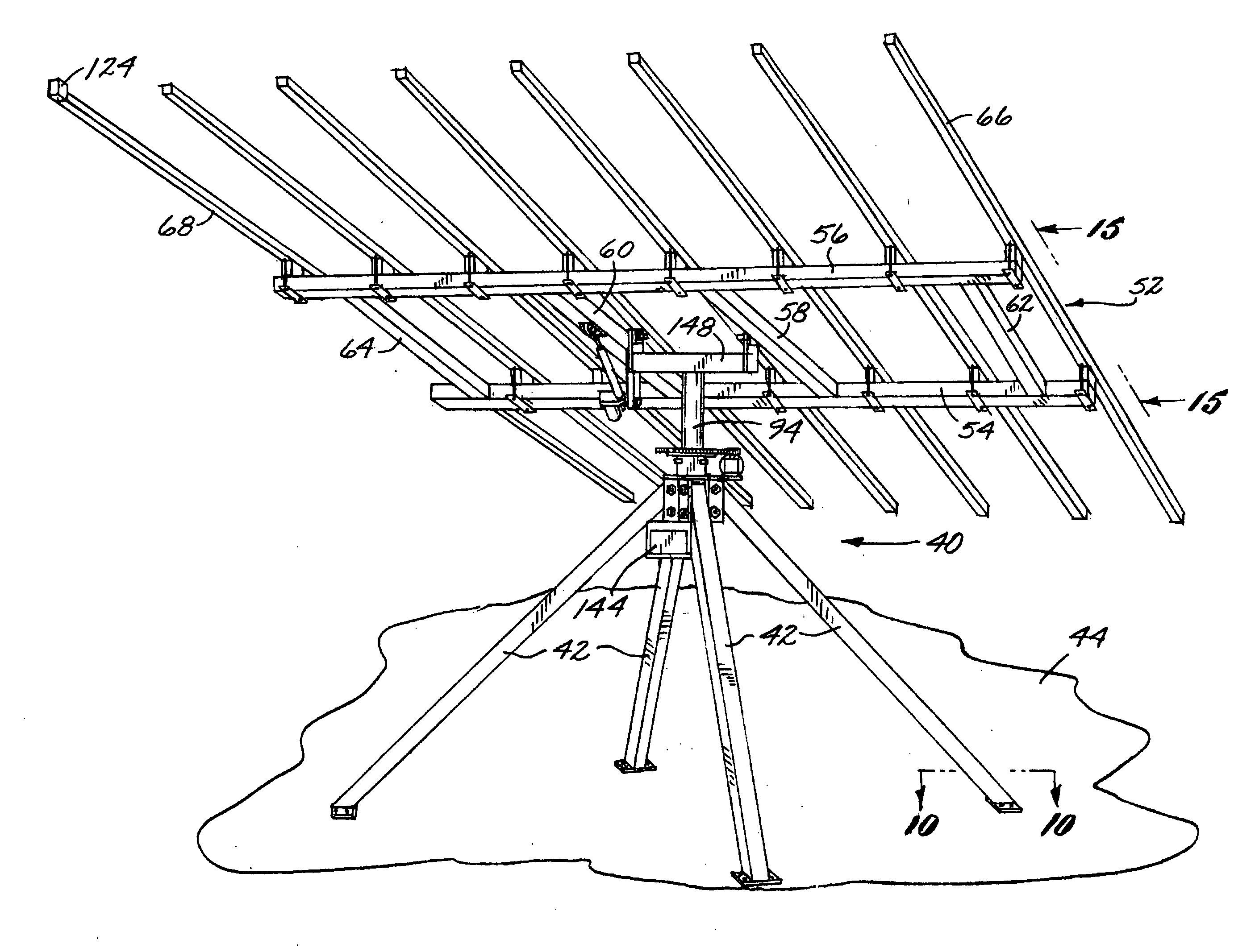
[0018]These and other objects and advantages are attained by a solar tracking mechanism and mounting platform for solar panels that is mounted with three or four legs attachable to a concrete pad and includes a substantially vertically disposed axle and a substantially horizontally disposed axle to which a plurality of panel support members are mounted to form a panel support assembly. The vertically disposed axle allows at least approximately 240 degree rotation of the panel support assembly to follow the daily East-West travel of the Sun in the sky. The substantially horizontally disposed axle allows declining or tilting of the panel support assembly for the North-South adjustment of the panel support assembly to correspond to the geographic latitude of the location where the solar tracking mechanism and platform is used.
[0019]The substantially horizontally disposed axle is placed on the centroid or substantially on the centroid location relative to the panel support members, including solar panels so that, as a result, the assembly is completely or substantially balanced and can be placed horizontally or in any inclined position without the weight of the assembly, including solar panels mounted thereon, causing it to precipitously drop or fall.
[0020]The objects and features of the present invention are set forth with particularity in the appended claims. The invention may be best understood by reference to the following description, taken in connection with the accompanying drawings wherein like numerals indicate like parts.

Problems solved by technology

The solar panels have substantial weight and because they are typically arranged in arrays of multiple panels, their combined weight can amount to several hundred or with wind loads to even several thousand pounds.
It should already be apparent from the foregoing that the mounting mechanism that is capable of supporting this much weight and is also capable of reliably allowing the North-South adjustment of panels and reliably performing or allowing the East-West daily movement of the panels is relatively complex itself.
In spite of the relatively large number of such disclosures of mounting and tracking apparatus for solar panels the mounting apparatus known in the present state-of-the-art still have some serious disadvantages in terms of the cost of installing them to a permanent location, their durability, particularly the durability of their East-West tracking and North-South tilting mechanism, and their ability to withstand wind pressures which can be very substantial.
Another serious problem in the prior art relates to the weight of the solar panels when a North-South declination or tilting is adjusted or maintained.
This uncontrolled drop or can seriously injure or even kill a person who may be hit by the combined weight of the panels and the may damage the entire mounting device and the panels themselves.
The state-of-the-art is aware that seriousness of this problem increases with the size and therefore with the weight of the array of panels.

Method used


Image

  • Balanced support and solar tracking system for panels of photovoltaic cells
  • Balanced support and solar tracking system for panels of photovoltaic cells
  • Balanced support and solar tracking system for panels of photovoltaic cells

Examples


Embodiment Construction

Preferred Embodiments

[0052]The following specification, taken in conjunction with the drawings, sets forth the preferred embodiments of the present invention. The embodiments of the invention disclosed herein are the best modes contemplated by the inventors for carrying out their invention in a commercial environment, although it should be understood that various modifications can be accomplished within the parameters of the present invention.

[0053]A perspective view of a preferred embodiment of the solar tracking assembly and mounting platform 40 is provided in FIG. 1 of the attached drawings. For the sake of brevity the solar tracking and mounting assembly may also be referred to simply as the “mounting apparatus”, “mounting platform”, “solar tracking apparatus” or the like. The first described two preferred embodiments have substantially the same construction with the difference being primarily that the first preferred embodiment includes equipment for automatically following the...


PUM


Abstract

A solar tracking mechanism and mounting platform for solar panels is mounted with three or four legs attachable to a concrete pad and includes a substantially vertically disposed axle and a substantially horizontally disposed axle to which a plurality of panel support members are mounted to form a panel support assembly. The vertically disposed axle allows at least 240 degree rotation of the panel support assembly to follow the daily East-West travel of the Sun in the sky. The substantially horizontally disposed axle allows declining or tilting of the panel support assembly for the North-South adjustment of the panel support assembly to correspond to the geographic latitude of the location where the solar tracking mechanism and platform is used. The substantially horizontally disposed axle is placed on the centroid or substantially on the centroid location relative to the panel support members, including solar panels so that, as a result, the assembly is completely or substantially balanced and can be placed horizontally or in any inclined position without the weight of the assembly, including solar panels mounted thereon, causing it to precipitously drop or fall.

Description

CLAIM OF PRIORITY OF PROVISIONAL APPLICATION[0001]The applicants claims priority of provisional application Ser. No. 61 / 200,550, filed on Dec. 1, 2008.BACKGROUND OF THE INVENTION[0002]1. Field of the Invention[0003]The present invention is in the field of support and tracking systems for an array of photovoltaic cells. More particularly, the present invention relates to a support and tracking system for an array of photovoltaic cells that is well balanced in the North-South declination sense and has numerous additional improvements over the state-of-the-art.[0004]2. Brief Description of the Prior Art[0005]The need to obtain reliable and renewable energy sources alternative to fossil fuels is greater at the present time than perhaps in any previous time in history. Electrical power generated from solar irradiation is a well known alternative and renewable energy source and the technology to exploit this source has been advancing rapidly during the last few decades. In the present sta...

Claims


Application Information

Patent Timeline
IPC IPC(8): F24J2/38F24S50/20
CPCF24J2/5233F24J2/542F24J2002/5462H02S20/00F24J2002/5493Y02E10/47Y02E10/50F24J2002/5465F24S25/13F24S30/452F24S2030/134F24S2030/135F24S2030/18H02S20/10H02S20/24H02S20/32Y02B10/10
Inventor WHIPPLE, GERALDWILLSEY, TOMMURPHY, SPENCERHOLMES, STERLING
Owner SUN A RAY
Learn More