
Lamp, lamp holder, and assembly of such a lamp and such a lamp holder

a lamp and lamp holder technology, applied in the direction of electric discharge lamps, coupling device connections, etc., can solve the problems of affecting the optical efficiency of the luminaire, the lamp base is relatively voluminous, and the connection of the lamp to the lamp holder is often complex, so as to facilitate the installation of the lamp and enhance the optical efficiency of the (less open) luminaire. , the effect of compact assembly

Inactive Publication Date: 2010-06-03
KONINKLIJKE PHILIPS ELECTRONICS NV
View PDF4 Cites 2 Cited by
  • Summary
  • Abstract
  • Description
  • Claims
  • Application Information

AI Technical Summary

Benefits of technology

[0004]This object can be achieved by providing an assembly according to the preamble, said lamp comprising at least one light-transmissive vessel being sealed at one single end by a lamp base, said lamp base being provided with a substantially annular flange enclosing an accommodating space for multiple current-supply conductors connected to said vessel, the annular flange being provided with coupling means, said lamp holder comprising at least one protruding portion being provided with counter-coupling means, and electrical contact members adapted to be electrically connected to the current-supply conductors of the lamp, the protruding portion of the lamp holder being adapted to engage the annular flange of the lamp for allowing the coupling means of the lamp to cooperate with the counter-coupling means of the lamp holder in a predefined mutual orientation of the lamp and the lamp holder. By applying an annular flange having a circularly-cylindrical shape (ring-shape), a rotational sliding engagement of the annular flange and the protruding portion will be allowed to position the lamp in the predefined orientation with respect to the lamp holder, which will facilitate installation of the lamp in a substantial manner. An inner surface and / or an outer surface of the annular flange will act as sliding surface for at least a part of the protruding portion during mutual displacement (rotation) of the lamp and the lamp holder. During engagement of the annular flange to the protruding portion, the lamp may be rotated along its longitudinal axis until the (at least one) predefined orientation of the lamp with respect to the lamp holder is obtained in which the coupling means and the counter-coupling means will be able to cooperate, leading to a proper coupling of the lamp to the lamp holder. Hence, by simply positioning the lamp base, in particular the flange, against the protruding portion of the lamp holder, and (in case the lamp has not yet been positioned in the predefined orientation) by subsequently axially rotating the lamp to the predefined orientation, a connection between the lamp and the lamp holder may be established. Since the lamp base provided with the annular flange, and the protruding portion may be constructed in a relatively compact manner, a relatively compact construction of the assembly may be achieved, which will enhance the optical efficiency of a (less open) luminaire in which the lamp holder may be incorporated. The exposed parts of the current-supply conductors are preferably fully positioned within the accommodating space defined by the flange to prevent or at least counteract damaging of the current-supply conductors.
[0005]In a preferred embodiment, the coupling means and the counter-coupling means are adapted to realise a coupling between the lamp and the lamp holder by (commonly linearly) translating the lamp with respect to the lamp holder along a longitudinal axis of the lamp followed by axially rotating the lamp. In this manner a solid and durable connection between the lamp and the lamp holder can be established in a relatively efficient manner. More in particular, the coupling means and the counter-coupling means together form at least one bayonet fitting, in which a translational and subsequent rotational movement have been incorporated. To improve the stability of the connection between the lamp and the lamp holder, the coupling means and the counter-coupling means together preferably form multiple bayonet fittings, in particular at least five bayonet fittings. It has been shown that the application of five (or more) bayonet fittings will facilitate locating the predefined orientation of the lamp, and hence will relatively easily lead to a relatively durable connection between the lamp and the lamp holder, such that a reliable contact between the current-supply conductors and the electrical contact members can be secured.
[0008]The annular flange may be integrated with the lamp base. However, in a preferred embodiment the annular flange is formed by a separate element being coupled, more preferably releasably coupled, to the lamp base. An advantage of applying a separate annular flange is that the annular flange preferably displays information related to at least one lamp characteristic, as a result of which a standard and simple lamp base can be manufactured after which the lamp-identifying flange is applied to the lamp base, which will commonly be advantageous from both a logistic and a financial point of view. The lamp characteristic can be exhibited by colour differentiation of the flange. It is also possible to display characteristic (technical) information onto the flange to indicate one or more lamp characteristics.

Problems solved by technology

The existing lamp base is relatively voluminous, in particular relatively long, which is detrimental to the optical efficiency of a luminaire surrounding the connected lamp.
Moreover, since the known lamp base has a rectangular cross-section, connection of the lamp to a lamp holder will commonly be complex as two connection possibilities will be available for a user, while commonly merely a single orientation of the lamp with respect to the lamp holder will lead to a proper position of said lamp with respect to said lamp holder, and in particular of the electrodes of both the lamp and the lamp holder.

Method used


Image

  • Lamp, lamp holder, and assembly of such a lamp and such a lamp holder
  • Lamp, lamp holder, and assembly of such a lamp and such a lamp holder
  • Lamp, lamp holder, and assembly of such a lamp and such a lamp holder

Examples


first embodiment

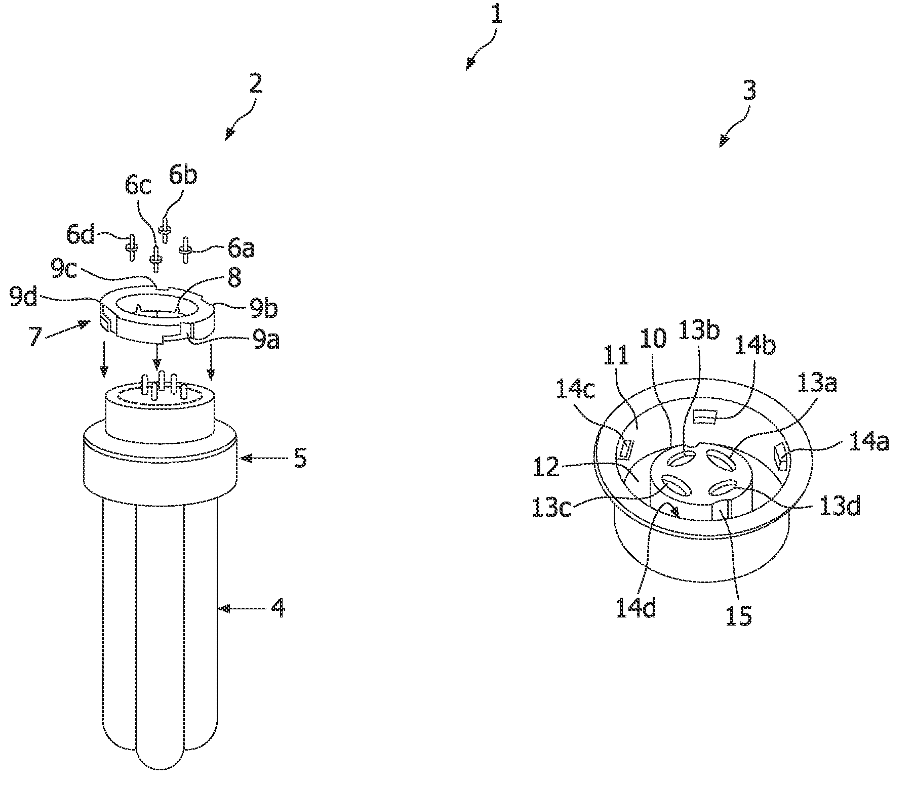
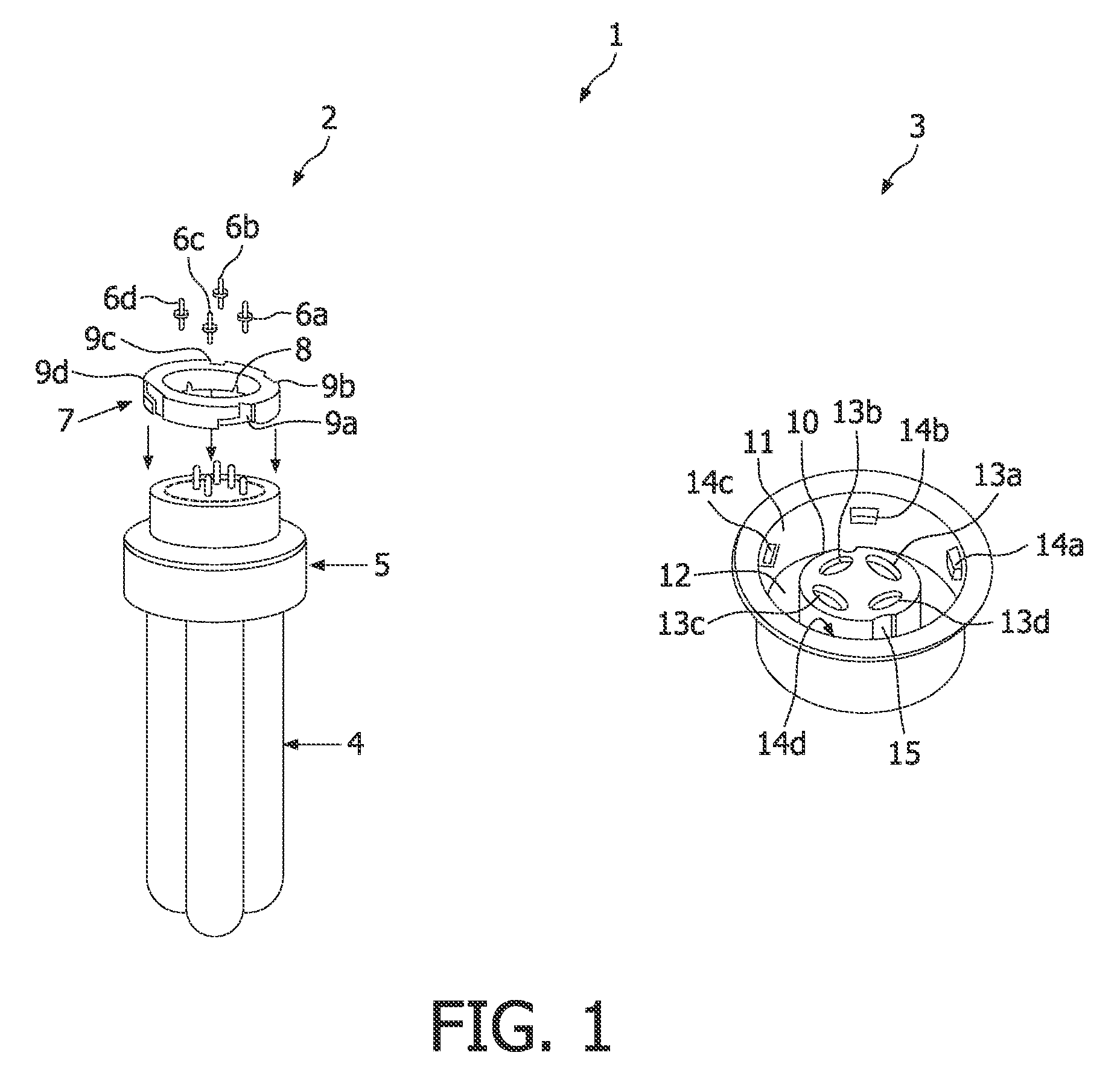
[0016]FIG. 1 shows a perspective view of an assembly 1 of a lamp 2 and a lamp holder 3 according to the invention. In this illustrative embodiment the lamp 2 is a compact fluorescent lamp (CFL) comprising a discharge vessel 4. The vessel 4 is sealed at one end by a lamp base 5. The lamp base 5 comprises four current-supply conductors 6a, 6b, 6c, 6d. The lamp 2 further comprises a coupling ring 7 which is attached to the lamp base 5 such that the current-supply conductors 6a, 6b, 6c, 6d are positioned within an accomodating space 8 defined within the ring 7. The ring 7 can have a particular colour indicating the type of lamp and / or the consuming power of the lamp 2. An outer surface of the ring 7 is provided with multiple angular slots 9a, 9b, 9c, 9d. The lamp 2 is adapted to be connected with the lamp holder 3. The lamp holder 3 comprises a central protruding portion 10 and a protruding collar 11 surrounding the central protruding portion 10. Between the central protruding portion 1...

second embodiment

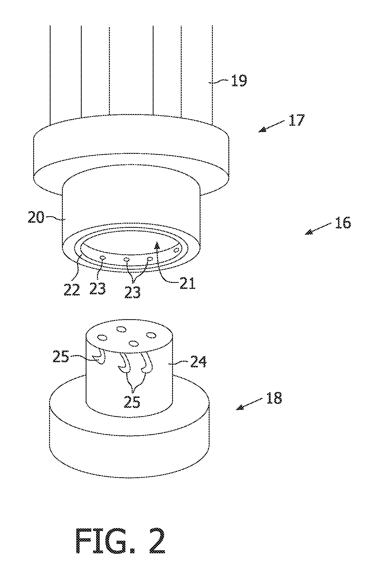
[0017]FIG. 2 shows a perspective view of an assembly 16 of a lamp 17 and a lamp holder 18 according to the invention. The lamp 17 comprises a light-transmissive vessel 19 and a lamp base 20. The lamp base 20 is provided with a receiving space 21 in which a connection ring 22 is applied, such that an outer surface of the connection ring 22 is attached to an inner surface of the lamp base 20. An inner side of the connection ring 22 is provided with projecting coupling elements 23. The lamp holder 18 comprises a protruding structure 24, which is adapted to be received in a tight-fitting manner by the receiving space 21 of the lamp 17. The protruding structure 24 is provided with multiple hooked slots 25 adapted for receiving the projecting coupling elements 23 for simultaneously realising multiple bayonet fittings between the lamp 17 and the lamp holder 18.

[0018]FIGS. 3a-3c show comparative sketches comparing a known lamp 26 and a lamp 27 according to the invention. FIG. 3a shows the u...


PUM


Abstract

The invention relates to an assembly of a lamp and a lamp holder. The invention also relates' to a lamp' for use in an assembly of a lamp and a lamp holder. The invention further relates to a lamp holder for use in an assembly of a lamp and a lamp holder. Assembly of a lamp (2) and a lamp holder (3), said lamp comprising at least one light-transmissive vessel (4) being sealed at one single end by a lamp base (5), said lamp base (5) being provided with a substantially annular flange enclosing an accommodating space for multiple current-supply conductors (6) connected to said vesel (4), wherein the annular flange is provided with coupling means (7), said lamp holder (3) comprising at least one protruding portion (10) being provided with counter-coupling means (14), and electrical contact members (13) adapted to be electrically connected to the current-supply conductors (6) of the lamp (2), wherein the protruding-portion (10) of the lamp holder (3) is adapted to engage the annular flange of the lamp (2) for allowing, the coupling means (7) of the lamp to cooperate with the counter-coupling, means (14) of the lamp holder (3) in a predefined mutual orientation of the lamp (2) and the lamp holder (3).

Description

FIELD OF THE INVENTION[0001]The invention relates to an assembly of a lamp and a lamp holder. The invention also relates to a lamp for use in such an assembly. The invention further relates to a lamp holder for use in such an assembly.BACKGROUND OF THE INVENTION[0002]Fluorescent lighting technology has been available for over 50 years and has been gradually supplanting conventional light bulbs, also known as incandescent bulbs, owing to their huge energy saving and four to six times higher efficiency to produce the same lumens as compared to the incandescent lamp. Compact fluorescent lamps (CFL) typically have a standardised lamp base acting as interface to connect the lamp to a lamp holder. The existing lamp base is relatively voluminous, in particular relatively long, which is detrimental to the optical efficiency of a luminaire surrounding the connected lamp. Moreover, since the known lamp base has a rectangular cross-section, connection of the lamp to a lamp holder will commonly...

Claims


Application Information

Patent Timeline
IPC IPC(8): H01J5/50
CPCF21V19/0095H01R33/7657H01R33/765H01R13/6456
Inventor BEMBRIDGE, MATHEW L.SCHRAVEN, ECKHARDT H.M.PIEPER, MARKUSVOGT, KARL-WILHELM
Owner KONINKLIJKE PHILIPS ELECTRONICS NV
Learn More