
Cooking grill

Inactive Publication Date: 2010-06-03
AFC BUSINESS VENTURES
View PDF32 Cites 55 Cited by
  • Summary
  • Abstract
  • Description
  • Claims
  • Application Information

AI Technical Summary

Problems solved by technology

Grills of the prior art suffer from many drawbacks.
However, every time the user opens the top of the cooking chamber, as is frequently necessary to insert, remove, or observe the food being cooked, all of the heat that has built up inside the cooking chamber that cooks the food by convection escapes and cooking by convection essentially halts.
Thus, opening the top of the cooking chamber slows down the overall cooking process and wastes fuel.
It also ultimately tends to lead to drier food when it is finally cooked.
Another drawback of conventional cooking grills is that, typically, only one type of cooking, namely, grilling, can be performed.
For instance, one cannot fry food in a conventional grill because there is no solid continuous surface on which the food can cook, only the grilling surface, which has openings in it.
Also, there is no convenient location in a conventional grill to place water for steaming food.
Yet another drawback of conventional cooking grills is that drippings from the food that is cooked on the grilling surface fall through the openings in the grilling surface onto the flame manifolds and / or the bottom of the cooking chamber.
This is undesirable because the food drippings tend to cause the flame manifolds or bottom surface of the housing to corrode over time.
If the user forgets to empty the container and the container overflows, it may damage the deck or other surface on which the cooking grill is placed.
Furthermore, as noted above, the container is positioned beneath the bottom of the cooking chamber and, therefore, typically is difficult to access.

Method used


Image

  • Cooking grill
  • Cooking grill
  • Cooking grill

Examples


Embodiment Construction

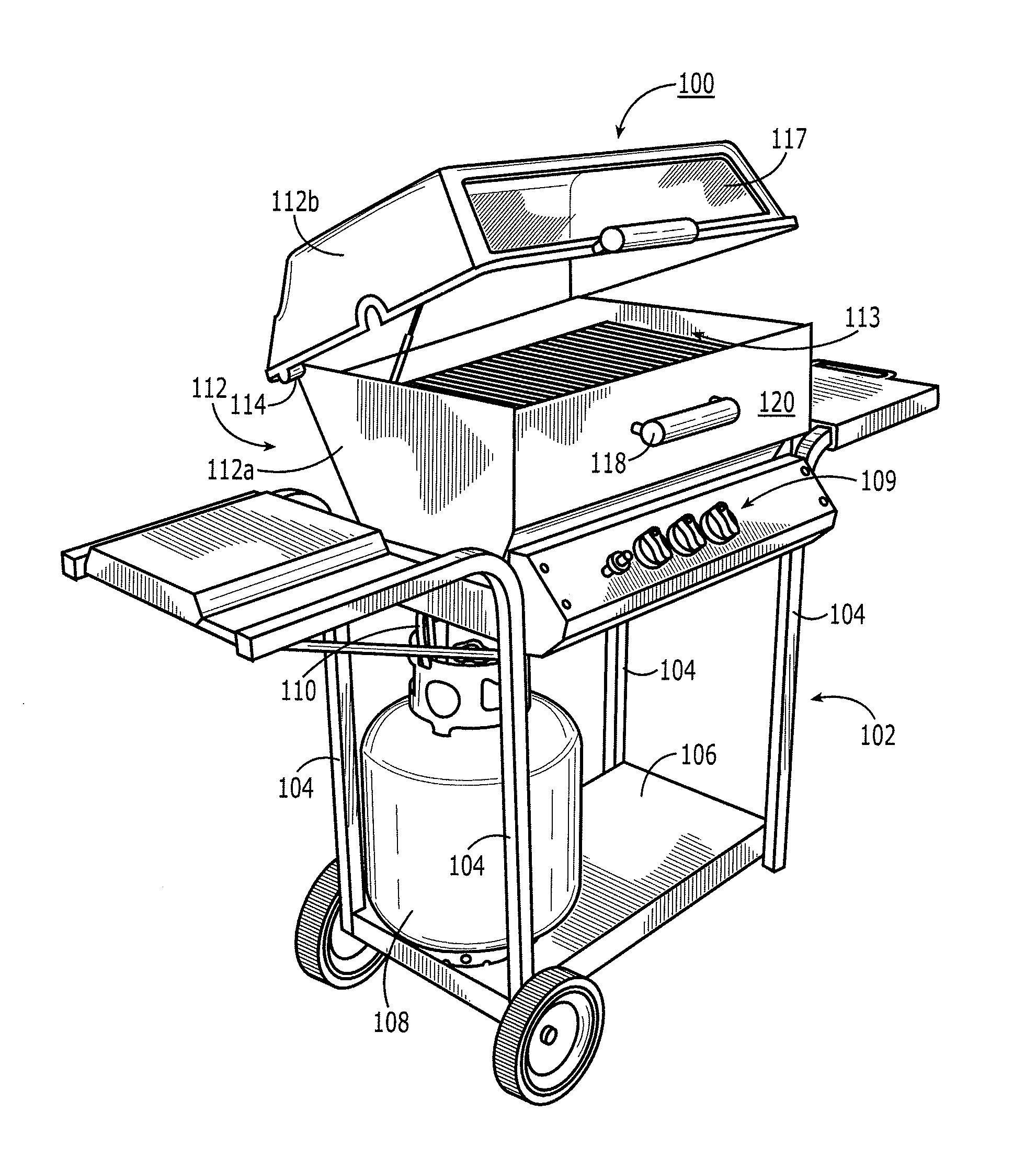
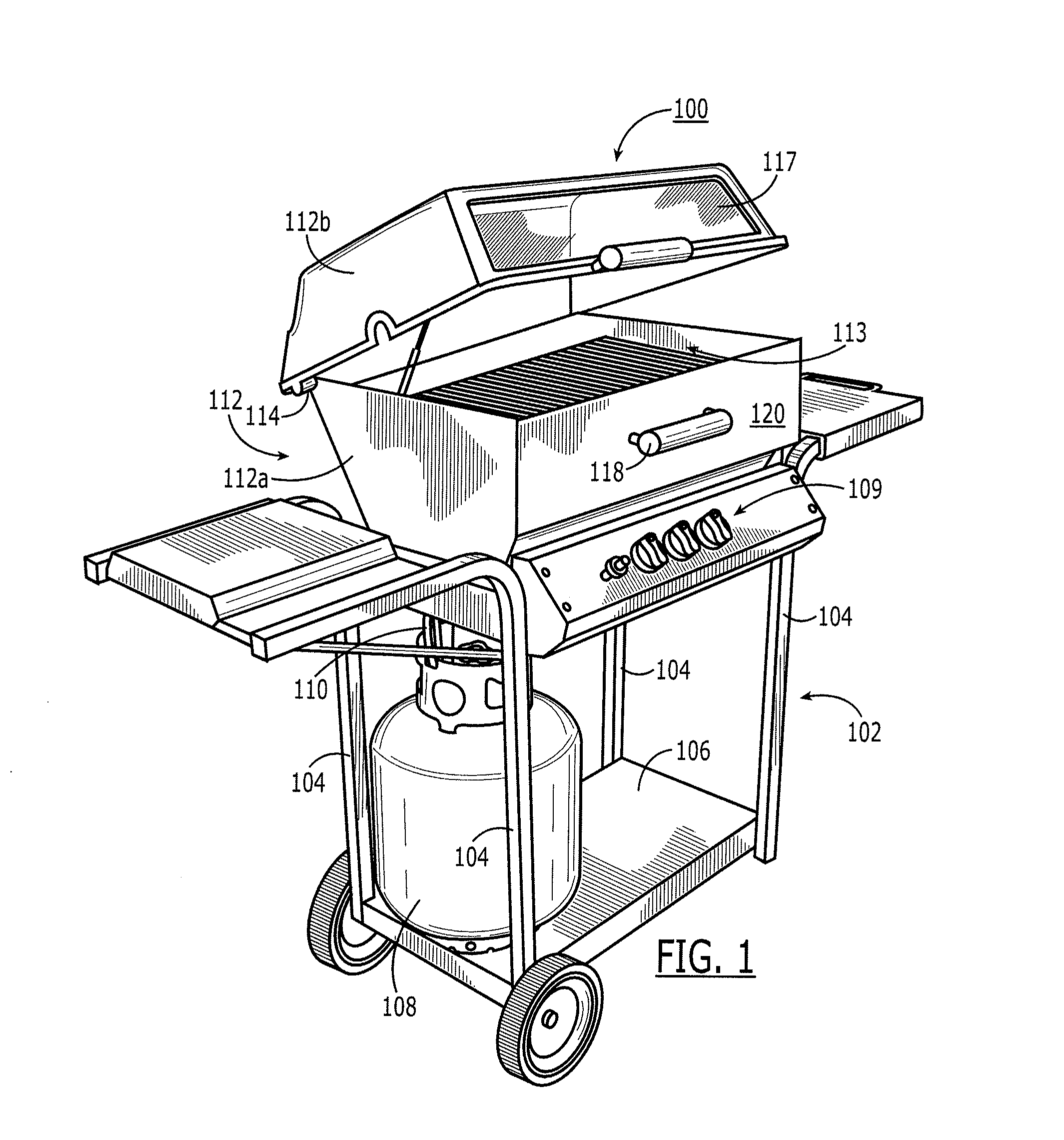
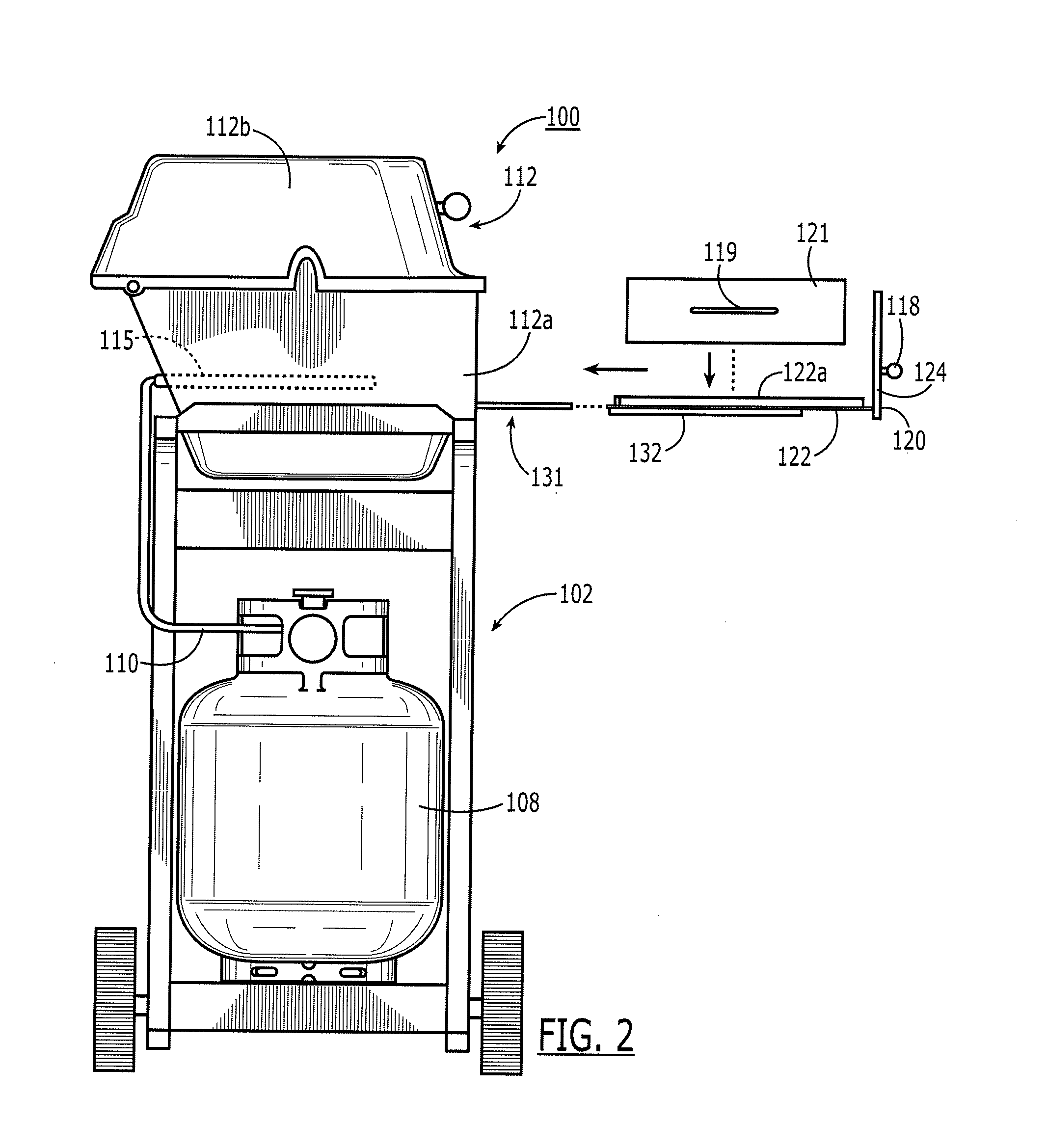
[0023]FIG. 1 is a perspective view of a grill in accordance with one particular embodiment of the present invention with the top of the grill partially opened for illustrative purposes. It should be understood that the grill would not normally be used with the top partially open, but with the top either fully open or fully closed. FIG. 2 is a partially-exploded, side view of the grill of FIG. 1 with the top closed and the side drawer open.

[0024]The grill 100 comprises a base or stand portion 102 comprising a plurality of legs 104 for supporting it on the ground or other horizontal surface and a shelf 106 for storage of items such as cooking supplies, cooking utensils, etc. The base 102 may be open, enclosed on one or more sides, or enclosed on all sides. If enclosed on all sides, preferably one of the sides includes or comprises a door for permitting access to the shelf or storage space. A fuel source, typically self-contained, such as a propane tank 108, is mounted somewhere on the...


PUM


Abstract

The invention is a cooking grill comprising a housing defining a cooking chamber and having a door therein hinged at a bottom thereof, a heating element disposed in the cooking chamber, a cooking surface slidably disposed to slide in and out of the housing through the door.

Description

CROSS-REFERENCE TO RELATED APPLICATIONS[0001]This application claims priority to provisional patent Application No. 61 / 160,423, filed Mar. 16, 2009 and is a continuation-in-part of application Ser. No. 11 / 866,691, filed Oct. 3, 2007, the disclosure of each of which is hereby incorporated herein by reference.BACKGROUND OF THE INVENTION FIELD[0002]The invention pertains to cooking grills.BACKGROUND[0003]Cooking grills are extremely popular in the United States and elsewhere for outdoor cooking during the warm months of the year. However, they also are often used indoors and / or during the colder months of the year.[0004]A conventional cooking grill comprises at least a cooking chamber, a grilling surface disposed in the cooking chamber, and one or more heating elements, such as a flame manifold and / or an infrared heater, proximate (typically beneath) the grilling surface within the cooking chamber. The cooking chamber is commonly provided by a metal housing comprising two parts configu...

Claims


Application Information

Patent Timeline
IPC IPC(8): A47J37/07F24C15/02
CPCA47J37/067A47J37/074A47J37/0786A47J2037/0795A47J37/07
Inventor CONTARINO, JR., ALFRED F.
Owner AFC BUSINESS VENTURES
Learn More