
Clavicle plate and screws

a technology of clavicle and screw, which is applied in the field of bone plates, can solve the problems of increased displacement, unsatisfactory patient-oriented outcome, and 15% non-union rate, and achieve the effect of reducing patient palpability and sufficient strength

Active Publication Date: 2010-05-27
NEW AMSTERDAM LLC
View PDF17 Cites 55 Cited by
  • Summary
  • Abstract
  • Description
  • Claims
  • Application Information

AI Technical Summary

Benefits of technology

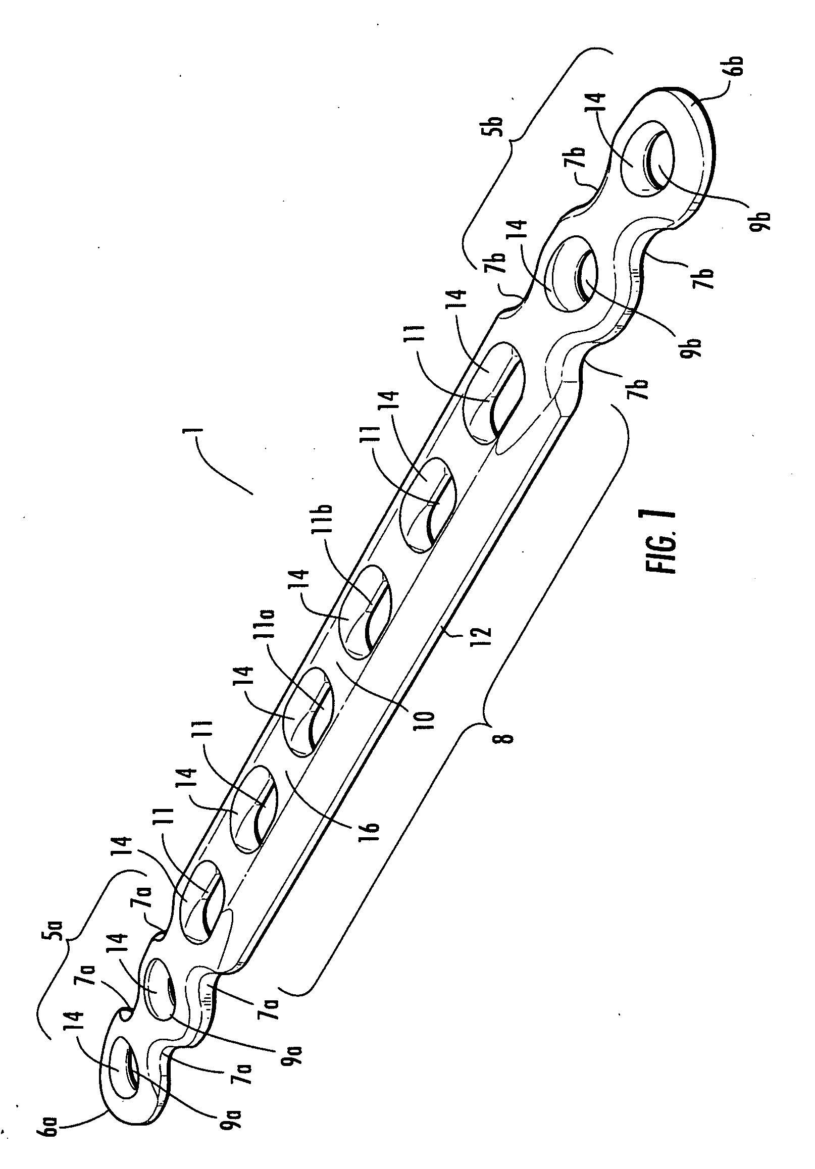
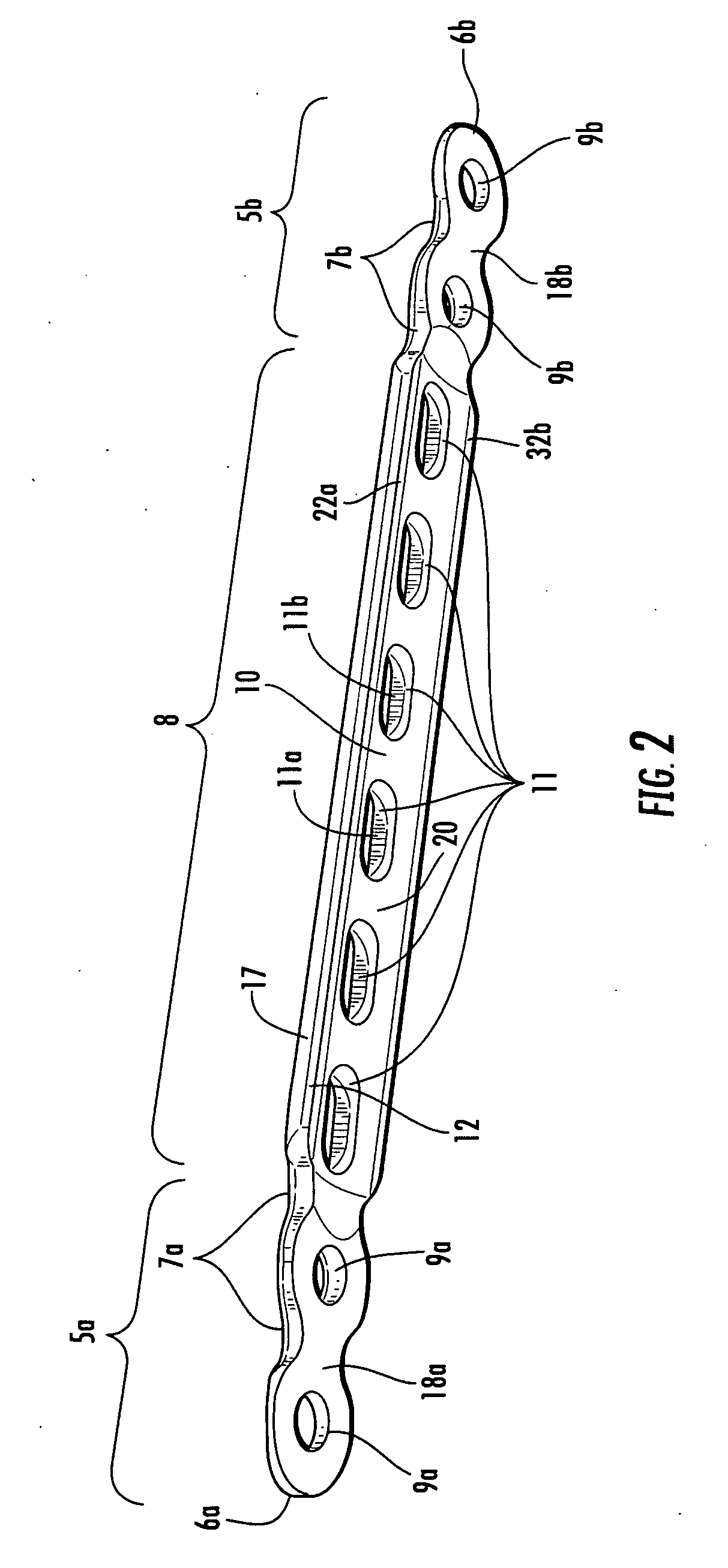
[0012]A bone plate and system is provided. The bone plate and system are particularly adapted to irregularly shaped bones such as the clavicle and the mandible. The fixation plate conforms to the contour of an irregularly shaped bone and eliminates the need for pre-bending or intraoperative bending of the plate. The bone plate is applied to the bone in a generally flat condition and the process of installing and tightening the bone screws in the prescribed order serves to contour the plate to the underlying bone while providing sufficient strength to effect bone healing. The plate profile and flexibility reduce patient palpability, particularly at the ends of the plate which are often the most critical.
[0013]The geometry of the plate allows the plate to follow the contour of an irregularly shaped bone, preventing prominence and patient palpability and streamlining the surgical procedure. The fragment screws allow the plate to be placed in closer contact with the bone than screws presently being used and the smaller profile of the fragment screws permits easier placement of the bone screws adjacent to the fracture. The system will provide a safe method of repairing discontinuities in a bone with complex curvature.
[0014]The bone plating system includes two or three types of implantable devices: a bone fixation plate; bone screws; and, fragment screws. The fragment screws (lag screws) are designed to prevent the plate from sitting on the head of the fragment screw thereby reducing the profile. The bone screws have an aggressive thread profile that allows the screw to firmly engage the bone and provide the compressive force necessary to bend the plate to the bone and provide secure postoperative fixation.

Problems solved by technology

Recent studies of displaced midshaft fractures of the clavicle, however, have shown a nonunion rate of 15% as well as a 31% unsatisfactory patient-oriented outcome.
This condition causes even greater displacement and more patient discomfort and deformity if treated by non-operative procedures.
When the clavicle is fractured, muscle and soft tissue forces are now unopposed and this often results in the ends of the clavicle displacing (or telescoping inwardly) and rotating relative to one another as the shoulder drops and rotates forward.
These forces make it difficult to realign (or reduce) a fractured clavicle so that a bone plate can be properly applied.
The complex shape of the clavicle makes it difficult for a surgeon to bend a flat plate in surgery to match the many contours of the bone.
Plates designed for a typical long bone do not fit the more complex contours of the clavicle bone and present a number of problems in fixing the plate to the bone in an acceptable manner.
Many of these plates are difficult to bend in general and are particularly difficult to bend at the ends of the plate—exactly where precise adaptation to the clavicle is desired.
The difficulty in doing so with a traditional long bone plate requires an unwanted expenditure of time and effort in the operating room particularly in light of the difficulty of reducing a displaced clavicle and maintaining that reduction.
While this precurvature generally mimics the profile of the clavicle, studies show that the variability in clavicles results in an inaccurate fit on clavicles in more than half the cases.
Moreover, the study only examined two dimensions and did not account for the curvature and twist of the clavicle surface in the third dimension.
While this may be applicable to typical long bones with a generally cylindrical shaft, the plate does not provide the needed three-dimensional contourability at its ends nor the reduced profile necessary for a complex and irregular bone such as a clavicle or a mandible.

Method used


Image

  • Clavicle plate and screws
  • Clavicle plate and screws
  • Clavicle plate and screws

Examples


Embodiment Construction

[0027]Overview

[0028]A bone fixation plate, a bone plating system, and method of plating a discontinuous bone of irregular shape are disclosed. The bone plating system includes two types of implantable devices: a bone fixation plate and bone screws. Optionally the system includes a third type of implantable device: fragment screws. As used herein, any reference to plate means bone fixation plate unless otherwise noted. Also as used herein any reference to screws includes both bone screws and fragment screws unless otherwise noted. The plate and screws of the plating system are especially suitable for midshaft displaced clavicle fractures. A midshaft displaced clavicle fracture is a fracture that occurs in the middle of the clavicle and one of the bone segments is displaced, the two bony ends generally being offset side-to-side and telescoped end-to-end. This also includes a fracture where there are more than two segments and one segment may be floating.

[0029]In operation the bone pla...


PUM


Abstract

A bone plate and system is provided. The bone fixation plate conforms to the contour of an irregularly shaped bone and eliminates the need for pre-bending or intraoperative bending of the plate. The bone plate is applied to the bone in a generally flat condition and the process of installing and tightening the bone screws in the prescribed order serves to contour the plate to the plate to the underlying bone while providing sufficient strength to effect bone healing. The geometry of the plate allows the plate to follow the contour of an irregularly shaped bone, preventing prominence and patient palpability and streamlining the surgical procedure.

Description

CROSS REFERENCE TO RELATED APPLICATION[0001]This application claims the benefit of U.S. patent application Ser. No. 12 / 276,544, filed Nov. 24, 2008, the entirety of which is hereby incorporated by reference into this application.BACKGROUND OF THE INVENTION[0002]1. Field of the Invention[0003]The invention relates to bone plates. More particular, the invention relates to bone plates and accompanying screws for repairing irregularly shaped bones such as the clavicle.[0004]2. Description of the Related Art[0005]Clavicle fractures account for approximately 2-5% of all fractures in the U.S. The majority of these clavicle fractures (approximately 75%) are located in the middle third of the clavicle, a very small percentage (<5%) in the medial third and the remainder in the lateral (or distal) third of the clavicle. Clavicle fractures have traditionally been treated non-operatively, even when one the fragments is substantially displaced. Clavicular nonunion was thought to be rare and of...

Claims


Application Information

Patent Timeline
Patent Type & Authority Applications(United States)
IPC IPC(8): A61B17/80
CPCA61B17/80A61B17/8061A61B17/863A61B17/8605A61B17/8085
Inventor RALPH, JAMES D.TROXELL, THOMAS N.MICHELS, MARKMEADE, THOMAS D.
Owner NEW AMSTERDAM LLC
Learn More