
Method to provide coil shaved metal fibers

a metal fiber and coil technology, applied in the field of metal fibers, can solve the problems of difficult if not impossible to provide machineable foils with thicknesses less than 35 m for a considerable number of metal alloys, difficult if not impossible to shave at a cutting rate less than about 10 m, and numerous process interruptions, etc., to achieve the effect of improving filter efficiency, reducing processing costs, and reducing processing costs

Inactive Publication Date: 2010-05-27
NV BEKAERT SA
View PDF3 Cites 2 Cited by
  • Summary
  • Abstract
  • Description
  • Claims
  • Application Information

AI Technical Summary

Benefits of technology

[0009]It is an object of the present invention to provide improved coil shaved metal fibers and methods of making the same. An advantage of the present invention is to provide coil shaved metal fibers having a smaller equivalent diameter as compared to presently known coil shaved metal fibers. It is an advantage of some embodiments of the present invention that the coil shaved metal fibers have a resistance to rupture in function of their equivalent diameter, which is improved as compared to the resistance to rupture in function of the equivalent diameter of presently known coil shaved metal fibers. Coil shaved metal fibers according to the present invention are less fragile. It is an advantage of some embodiments of the present invention that the coil shaved metal fibers have less rough fiber surfaces, also known as mantle surface of the fiber.

Problems solved by technology

The presently known coil shaved fibers have several disadvantages, which disadvantages are linked to process limitations of the presently known processes for shaving metal fibers from a coiled metal foil.
Although some metal foils of 10 μm thickness are known, the provision of machineable foils with thicknesses of less than 35 μm is difficult if not impossible for a considerable number of metal alloys.
On the other hand, it seems to be difficult if not impossible to shave at a cutting rate of less than about 10 μm.
When the foil is too thin, or the cutting rate is too small, the shaving operation is subjected to numerous process interruptions, i.e. broken bundles of metal fibers.
It is believed that these ruptures of coil shaved fibers are due to upsetting of the fiber surface due to the shaving operation itself.
It is found that coil shaved metal fibers are rather uneven, especially along the sides which have been in contact with the cutting tool during shaving.
In spite of their relatively large equivalent diameter, coil shaved metal fibers as presently known are rather fragile, which is also believed to be due to the upset at the fiber surface and the creation of numerous weak spots.
This large deviation renders the bundles of coil shaved metal fibers not useful for particular applications, and necessitates the use of more expensive bundle drawn metal fibers with this equivalent diameter.

Method used


Image

  • Method to provide coil shaved metal fibers
  • Method to provide coil shaved metal fibers
  • Method to provide coil shaved metal fibers

Examples


first embodiment

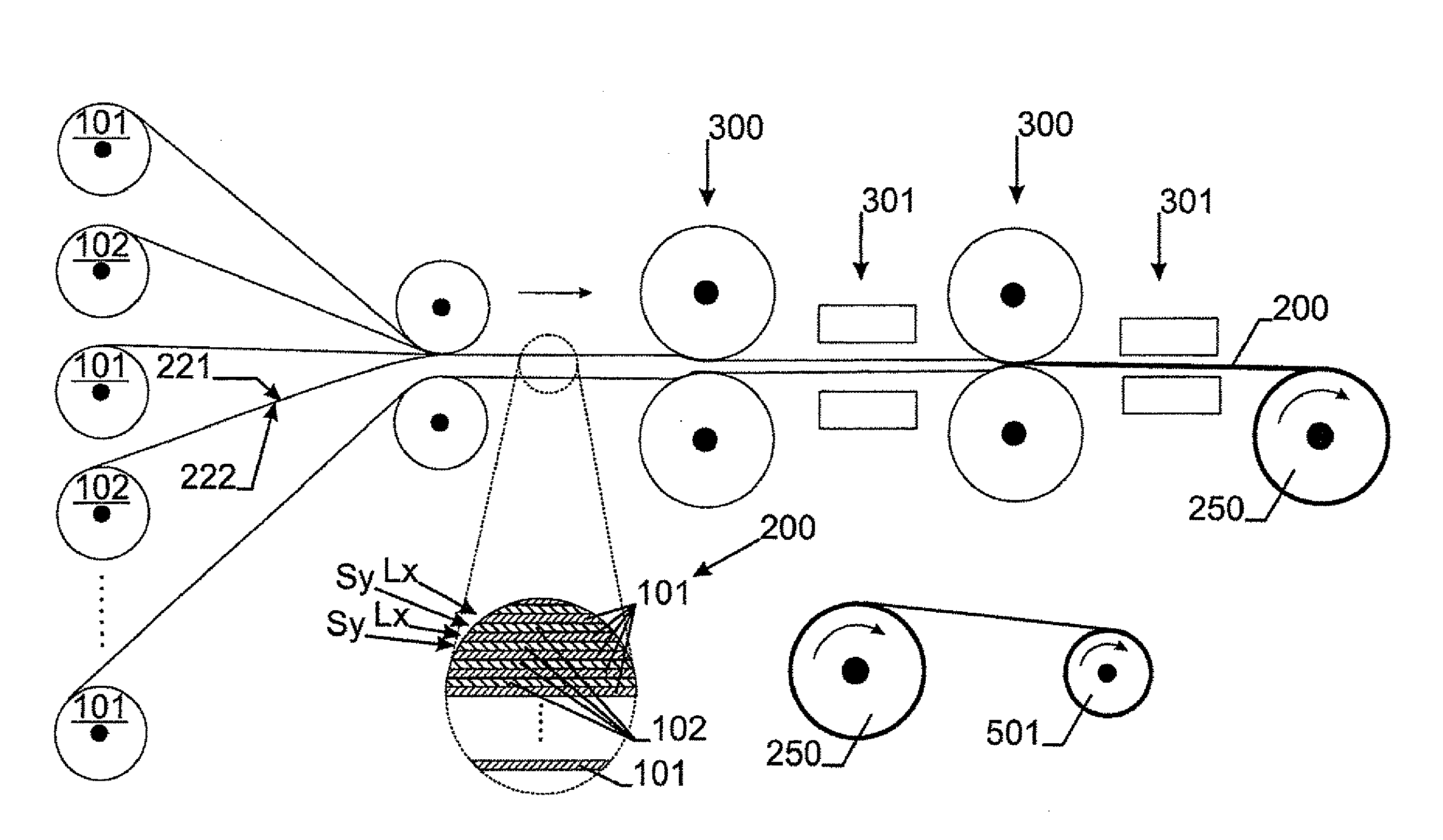
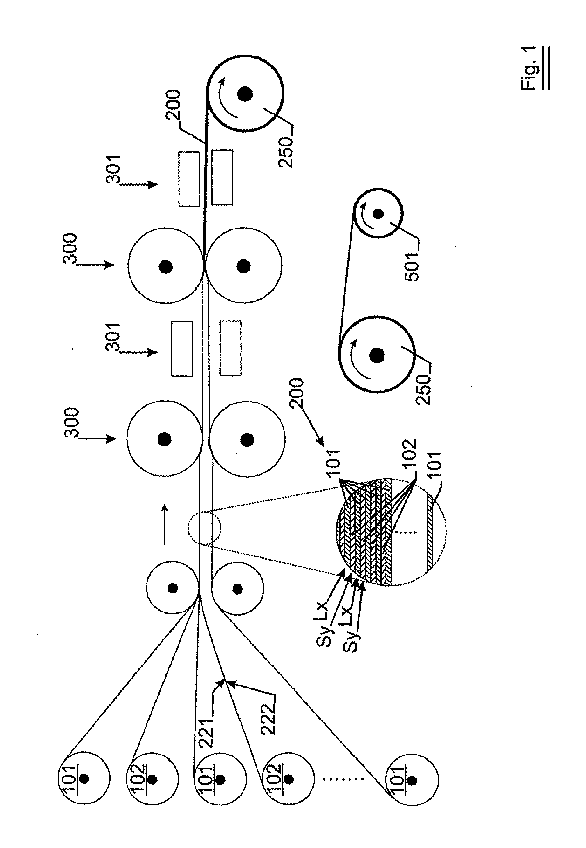
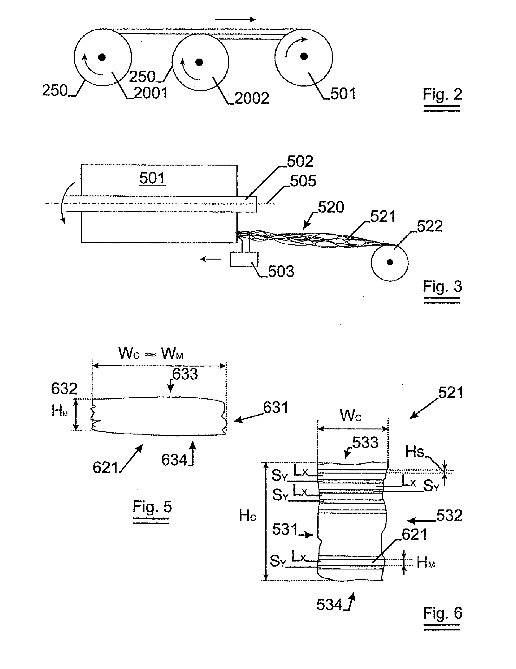
[0072]FIG. 1, FIG. 2, FIG. 3 and FIG. 4 together show a schematic representation of the steps of a method to provide a coil shaved metal fiber according to the present invention.

[0073]As shown in FIG. 1, a composite metal foil with a desired composition and thickness is provided.

[0074]A number of metal foils 101, out of which metal fibers are to be made, are provided. A number of foils 102 of sacrificial metal, such as Cu, are provided as well. The foils are stacked in such a way that between each pair of adjacent metal foils 101, a sacrificial metal foil 102 is provided. The foils are stacked or layered in order to provide a metal composite foil 200, the metal composite foil comprising at least two metal layers Lx for being converted into metal fibers and being provided by the metal foils 101. Between each pair of adjacent metal layers, a sacrificial layer Sy is provided from a sacrificial metal, each sacrificial layer being provided by one of the sacrificial metal foils 102.

[0075]...

second embodiment

[0096]The coil shaved metal fibers according to the present invention may be used to provide metal fiber fleeces, such as metal fibers sintered fleeces or structures for use as burner surface, e.g. radiant gas burner surfaces, or filter media for filtration of fluids such as liquids or gases. The metal fiber fleeces, such as metal fibers sintered fleeces or structures may be used for diesel exhaust filtration or purification or for acoustic damping purposes. As the deviation on fiber equivalent diameter is smaller, the deviation on air permeability of the fleece is reduced as compared to prior art.


PUM

PropertyMeasurementUnit
thicknessaaaaaaaaaa
thicknessaaaaaaaaaa
thicknessaaaaaaaaaa

Abstract

A method for providing coil shaved metal fibers according to the present invention comprises the steps of -providing a metal composite foil, the metal composite foil comprising oat least two metal layers (Lx) for being converted into metal fibers, each pair of adjacent metal layers are mutually separated by a sacrificial layer (Sy) provided from a sacrificial metal, each sacrificial layer (Sy) having a first and second surface, whereby for each sacrificial layer, the first surface contacts one of the pair of adjacent metal layers, the second surface is contacting the other of the pair of adjacent metal layers; -coiling said metal composite foil on a shaft thereby providing a metal coil having one free end surface; -rotating the metal coil and cutting the free end surface of the metal coil by means of a cutting tool, thereby providing a bundle of composite fibers; -removing the sacrificial metal of the sacrificial layers from the composite fibers thereby providing a bundle of metal fibers, each metal fiber being obtained from one of the metal layers (Lx).

Description

TECHNICAL FIELD OF THE INVENTION[0001]The present invention relates to metal fibers, more particular to coil shaved metal fibers and to a method to provide coil shaved metal fibers.BACKGROUND OF THE INVENTION[0002]Coil shaved metal fibers are known in the art from U.S. Pat. No. 4,930,199. Coil shaved fibers comprising several layers of different metals or metal alloys are known from WO2005 / 028135A1. Coil shaved metal fibers typically have a substantially rectangular cross section, due to the process of coil shaving. This is different from e.g. bundle drawn metal fibers, which have usually a pentagonal or hexagonal cross section. The coil shaved metal fibers also differ from other machined metal fibers such as steel wool. Steel wool usually has a rather triangular cross section.[0003]The presently known coil shaved fibers have several disadvantages, which disadvantages are linked to process limitations of the presently known processes for shaving metal fibers from a coiled metal foil...

Claims


Application Information

Patent Timeline
Patent Type & Authority Applications(United States)
IPC IPC(8): B32B5/02B32B15/02B23P17/06B26D7/08B22F1/062
CPCB21C37/047B22F1/004B22F3/002B23P17/06Y10T29/142Y10T428/12424Y10T29/143Y10T82/10Y10T428/12431Y10T29/14Y10T83/0405B22F1/062
Inventor DE BONDT, STEFAANSCHILDERMANS, INGE
Owner NV BEKAERT SA
Learn More