
Power wheel chair

a power wheel chair and wheel chair technology, applied in the field of vehicles, can solve the problems of poor design of the handle for pushing a conventional manual wheelchair, many attendants and caregivers incur back, neck, leg and carpal tunnel injuries, etc., and achieve the effect of improving motion control

Inactive Publication Date: 2010-05-27
FLOWERS IP
View PDF20 Cites 4 Cited by
  • Summary
  • Abstract
  • Description
  • Claims
  • Application Information

AI Technical Summary

Benefits of technology

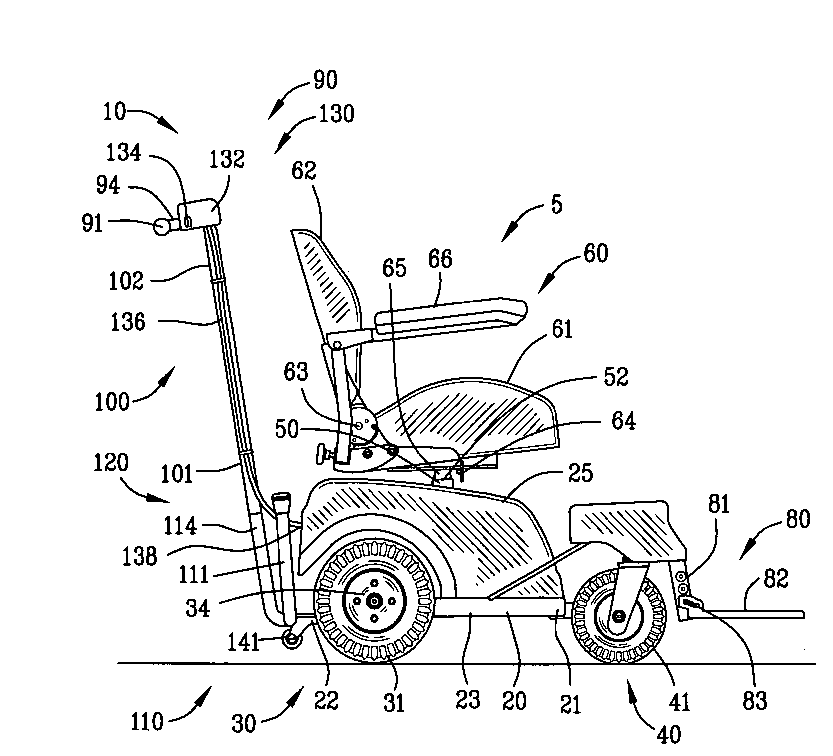
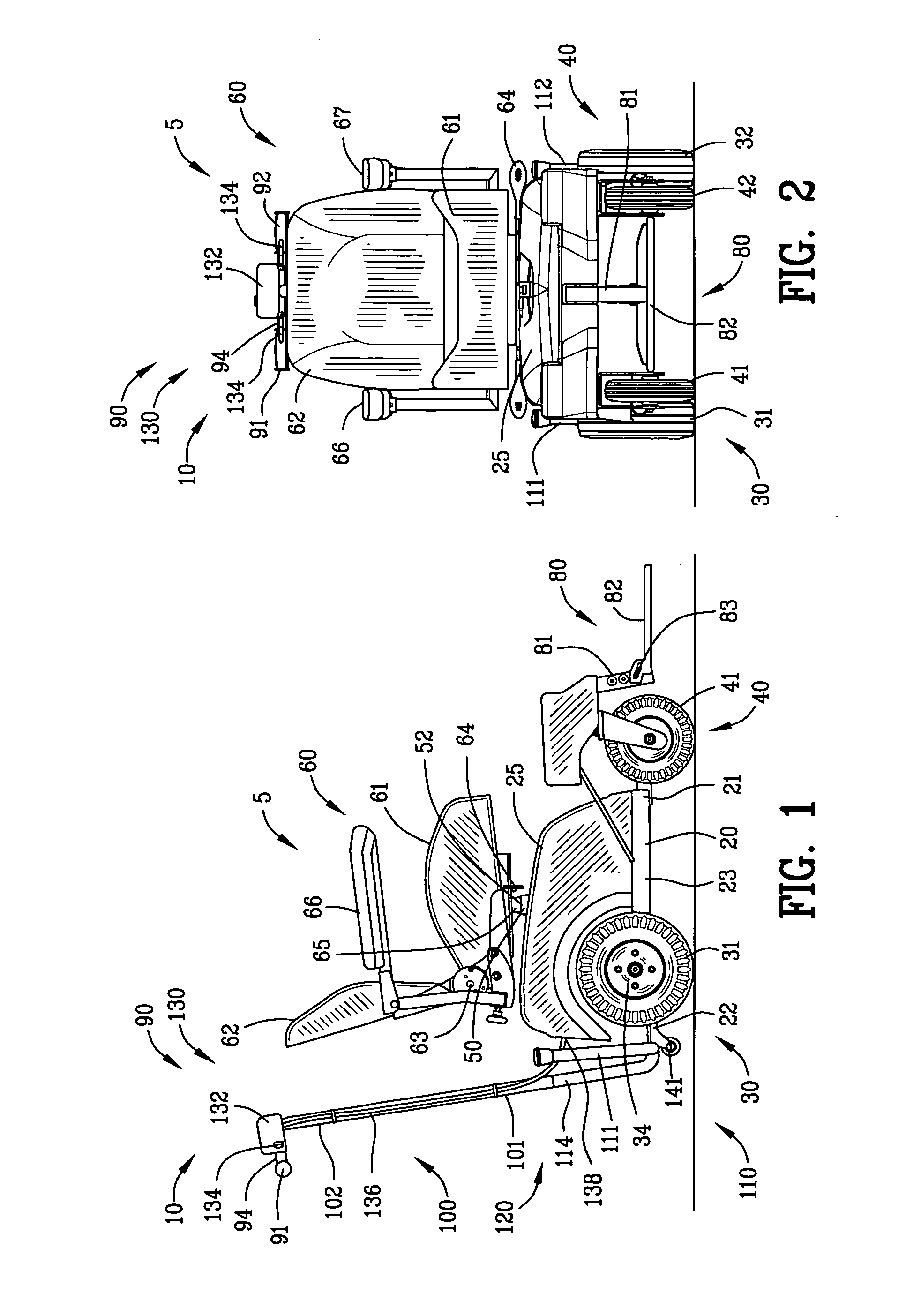
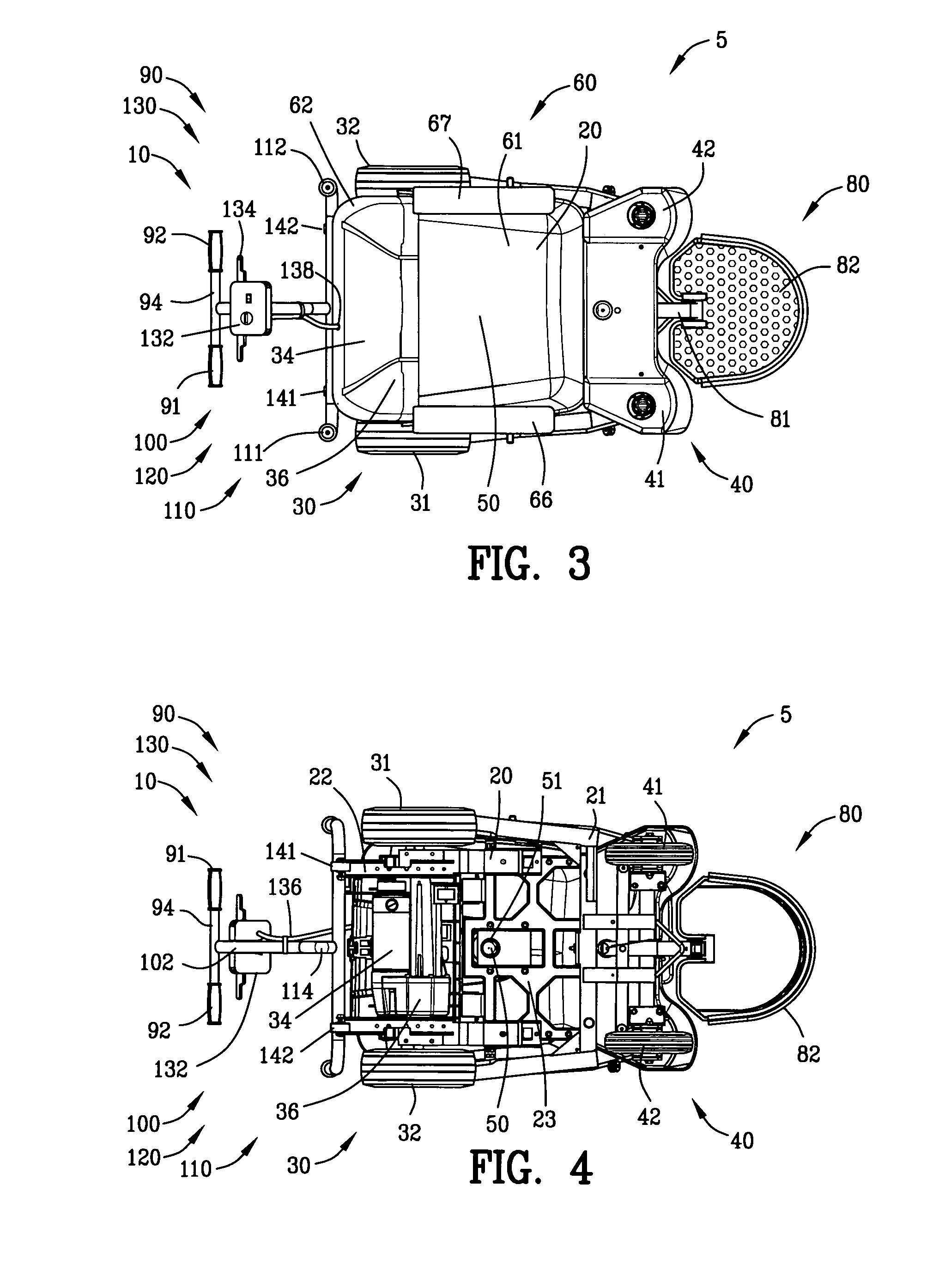
[0021]The present invention is defined by the appended claims with specific embodiments being shown in the attached drawings. For the purpose of summarizing the invention, the invention relates to a power wheel chair having an improved motion control comprising a frame having a right frame section and a left frame section extending between a front frame end and a back frame end. A seat is mounted to the frame for transporting an occupant. A right and a left caster wheel is located in proximity to the front frame end adjacent to the right and left frame sections, respectively. A right and a left drive wheel are located in proximity to the rear frame end adjacent to the right and left frame sections, respectively. A motor drives the right and left drive wheels through a differential gearbox. A right and a left handle are connected to the right and left frame sections, respectively, for enabling an attendant to steer the power wheel chair. An electronic control has a control lever located in proximity to one of the right and left handles for enabling the attendant to control the speed and braking of the power wheel chair.

Problems solved by technology

The handles for pushing a conventional manual wheelchair are poorly designed from an ergonomic standpoint for pushing by an attendant or a caregiver.
Many attendants and caregivers incur back, neck, leg and carpal tunnel injuries from pushing a conventional manual wheelchair.
Since many of the caregivers are spouses of an elderly disabled person, the spouses are at higher risk for heart attacks and accidental falls that can cause serious injury to both the attendant and wheelchair occupant.
Frequently, the attendant / caregiver fails to engage the parking brakes of a conventional manual wheelchair when the occupant is getting on or off of the conventional manual wheelchair that leads to further injuries.
Furthermore, since the parking brakes are located on the front of the manual wheelchair, an attendant cannot engage the parking brakes while the wheelchair is in motion such as descending a ramp.
Typically, the cost of a powerchair personal mobility vehicle is greater than the cost of a scooter personal mobility vehicle due to the cost of plural electric motors in addition to the increased cost of a joystick operated dual-motor differential control relative to the single motor speed control of the scooter personal mobility vehicle.
Unfortunately, it is difficult to operate a joystick of a powerchair vehicle while walking behind the seat of the powerchair.
Because of the cost of a secondary joystick and the difficulty in operating the joystick control of the powerchair from behind the seat, the use of these optional attendant joysticks have not find widespread use in the art.

Method used


Image

  • Power wheel chair
  • Power wheel chair
  • Power wheel chair

Examples


second embodiment

[0086]FIG. 11 is a side view of a power wheel chair 5A incorporating an improved motion control 10A of the present invention. In this example, the power wheel chair 5A comprises a frame 20A extending between a first frame end 21A and a second frame end 22A. A drive wheel assembly 30A comprises a right and left drive wheel 31A and 32A located in proximity to the second end 22A of the frame 20. A caster wheel assembly 40A comprising a right and a left caster wheel 41A and 42A is located in proximity to the first frame end 21A of the frame 20A. The steering bar 90A is secured to in proximity to the first end 21A of the frame 20A.

[0087]The steering bar 90A is mounted to the first frame end 21A of the frame 20A through an upstanding portion 100A and a frame mounting 110A through a coupling 120A in a manner similar to FIGS. 1-6. The second embodiment of a power wheel chair 5A provides a front wheel drive in contrast to the rear wheel drive shown in FIGS. 1-6.

[0088]The front wheel drive po...

third embodiment

[0089]FIGS. 12-14 are various views of a power wheel chair 5B incorporating an improved motion control 10B of the present invention. The power wheel chair 5B comprises a frame 20B extending between a first frame end 21B and a second frame end 22B. A drive wheel assembly 30B comprises a right and a left drive wheel 31B and 32B located in proximity to the second end 22B of the frame 20B. A single drive motor 34B drives the right and left drive wheels 31B and 32B through a differential gearbox 36B in a manner similar to FIGS. 1-6. A caster wheel assembly 40B is located in proximity to the first frame end 21B of the frame 20B. The caster wheel assembly 40B comprises a right and a left caster wheel 41B and 42B. The right and left caster wheels 41B and 42B are shown as right and left caster wheels mounted by swivels to the first frame end 21B of the frame 20B.

[0090]A steering bar 90B is secured to the power wheel chair 5B for controlling the power wheel chair 5B. In this embodiment, the s...


PUM


Abstract

A power wheel chair is disclosed having an improved motion control comprising a frame having a seat for transporting an occupant. A right and a left caster wheel are located in proximity to a front frame end. A right and a left drive wheel are located in proximity to a rear frame end. A motor drives the right and left drive wheels through a differential gearbox. A right and a left handle are connected to frame for enabling an attendant to steer the power wheel chair. An electronic control has a control lever located in proximity to one of the right and left handles for enabling the attendant to control the speed and braking of the power wheel chair.

Description

CROSS-REFERENCE TO RELATED APPLICATIONS[0001]This application is a continuation-in-part of U.S. patent application Ser. No. 12 / 454,751 filed May 22, 2009. Application Ser. No. 12 / 454,751 filed May 22, 2009 claims benefit of U.S. Patent Provisional application No. 61 / 128,556 filed May 22, 2008. All subject matter set forth in provisional application No. 61 / 128,556 filed May 22, 2008 and application 12 / 454,751 filed May 22, 2009 is hereby incorporated by reference into the present application as if fully set forth herein.BACKGROUND OF THE INVENTION[0002]1. Field of the Invention[0003]This invention relates to vehicles and more particularly to a power wheel chair having an improved motion control.[0004]2. Description of the Related Art[0005]Attendant operated patient transport vehicles may be characterized as either a manual wheelchair type or a powerchair personal mobility vehicle type with a joystick attendant control. Each of these transport vehicles has certain advantages and disad...

Claims


Application Information

Patent Timeline
Patent Type & Authority Applications(United States)
IPC IPC(8): B60K26/00
CPCA61G5/042A61G5/045A61G2005/048A61G2203/14A61G2005/0891A61G2005/125A61G2005/128A61G2005/0825A61G5/048A61G5/125A61G5/128
Inventor FLOWERS, MICHAEL J.FLOWERS, JORDAN M.
Owner FLOWERS IP
Learn More