


Quick Research
Generate reliable direction feasibility study reports for your R&D in just a few steps.

Technical Q&A
Discover and master advanced knowledge NOW. Basics, ideas, possibilities, all at once.

Find Solutions
As an expert in R&D theories, this can generate solutions to your technical problems instantly.

Evaluate Feasibility
Analyze your overall solution with one click, know your potential R&D risks in advance.

Monitor Landscape
Get weekly tech updates, stay abreast of the latest tech innovations and key insights.
Downhole decelerating device, system and method
a decelerating device and downhole technology, applied in the direction of drilling casings, drilling pipes, borehole/well accessories, etc., can solve the problems of ineffective prior art shock absorption configurations
- Summary
- Abstract
- Description
- Claims
- Application Information
AI Technical Summary
Problems solved by technology
Method used
Image

Examples
Embodiment Construction
[0011]A detailed description of one or more embodiments of the disclosed apparatus and method are presented herein by way of exemplification and not limitation with reference to the Figures.
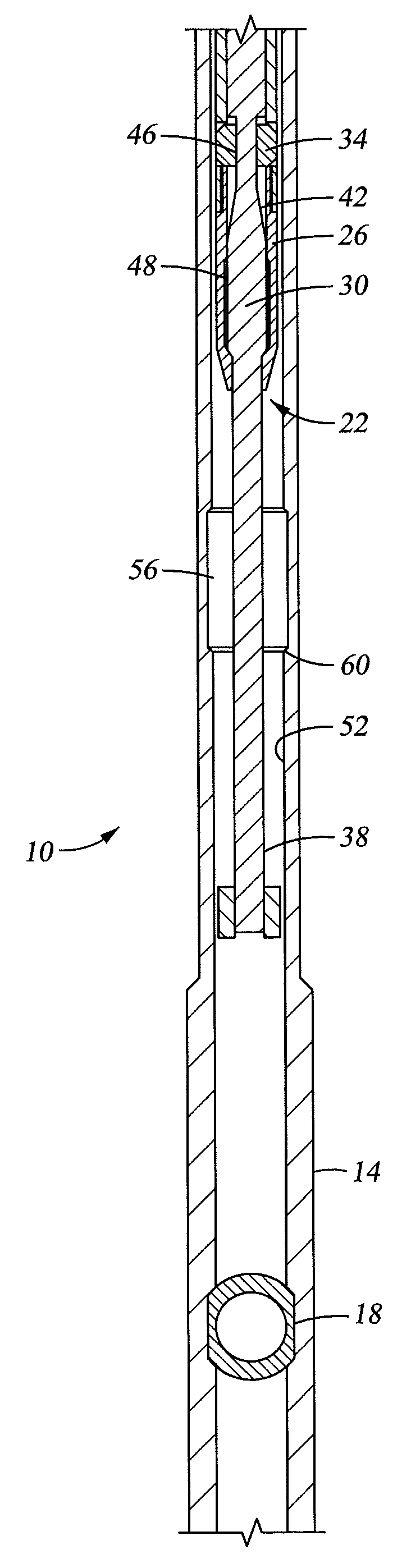
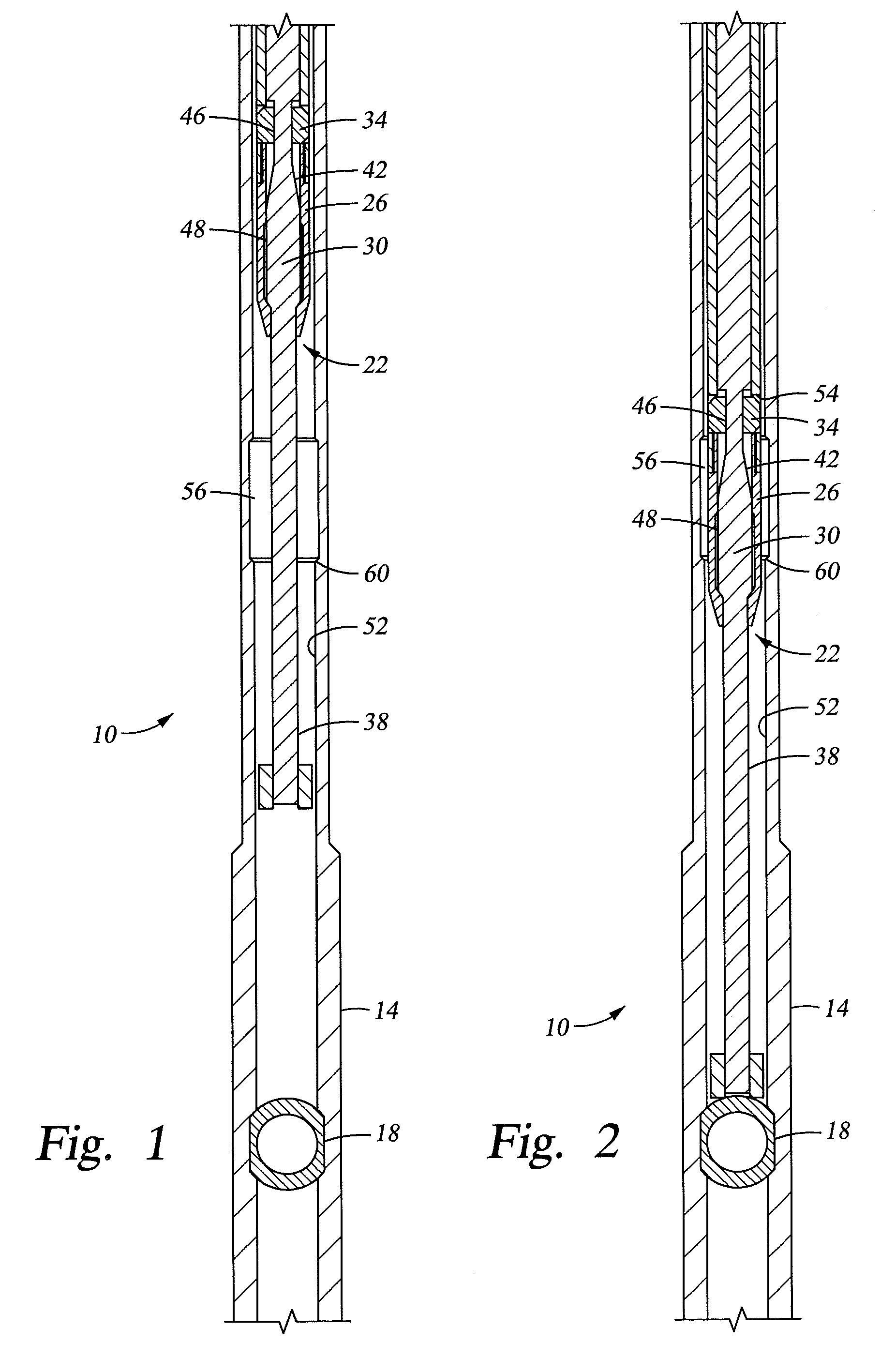
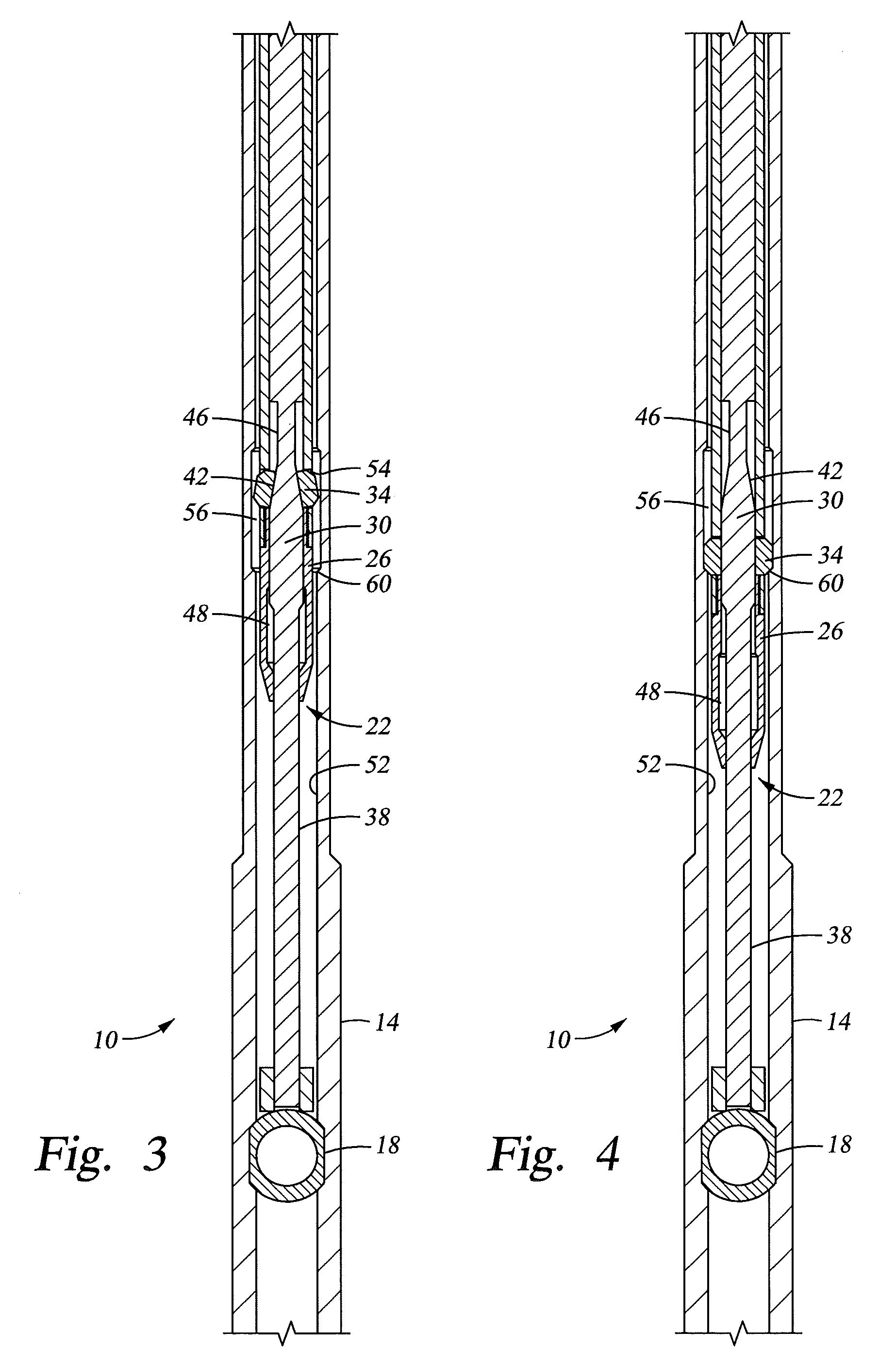
[0012]Referring to FIG. 1, a decelerating system 10 disclosed herein is illustrated. The system 10 includes, a downhole tubular 14 with a downhole structure 18, depicted herein as a ball valve, positioned therein, and a decelerator assembly 22. In addition to the body 26, the decelerator assembly 22 includes, a mandrel 30 and at least one radially movable element 34 also referred to herein as a dog. A biasing member such as a tension spring (not shown) biases the dog(s) 34 radially inwardly toward the mandrel 30, which extends longitudinally beyond the dog(s) 34 in both directions. The mandrel 30 is longitudinally movable relative to the body 26, and the dog(s) 34, and has a distal end 38 that extends well beyond the body 26, in a downhole direction as illustrated herein. A tapered portion 42 of ...
PUM
 Abstract
Description
Claims
Application Information
 - R&D Engineer
- R&D Manager
- IP Professional
- Industry Leading Data Capabilities
- Powerful AI technology
- Patent DNA Extraction
Browse by: Latest US Patents, China's latest patents, Technical Efficacy Thesaurus, Application Domain, Technology Topic, Popular Technical Reports.
© 2024 PatSnap. All rights reserved.Legal|Privacy policy|Modern Slavery Act Transparency Statement|Sitemap|About US| Contact US: help@patsnap.com