
Method for displaying continuous lines

a continuous line and line array technology, applied in the field of continuous line arrays, can solve the problems of complex conversion, high cost of new hardware components development, and high computation intensity of methods such as these, so as to avoid complex conversion

Active Publication Date: 2010-05-20
DIEHL AEROSPACE GMBH
View PDF23 Cites 0 Cited by
  • Summary
  • Abstract
  • Description
  • Claims
  • Application Information

AI Technical Summary

Benefits of technology

[0011]In consequence, the object of the present invention is considered to be the development of a method of the generic type mentioned initially for displaying continuous lines, which allows a high-quality display of continuous lines, with a finite line width, with as little computation complexity and time involved as possible.

Problems solved by technology

While the software, such as the “Standard Graphics Language” (SGL) is being developed further all the time, the development of new hardware components is extraordinarily costly, particularly for civil and military aviation.
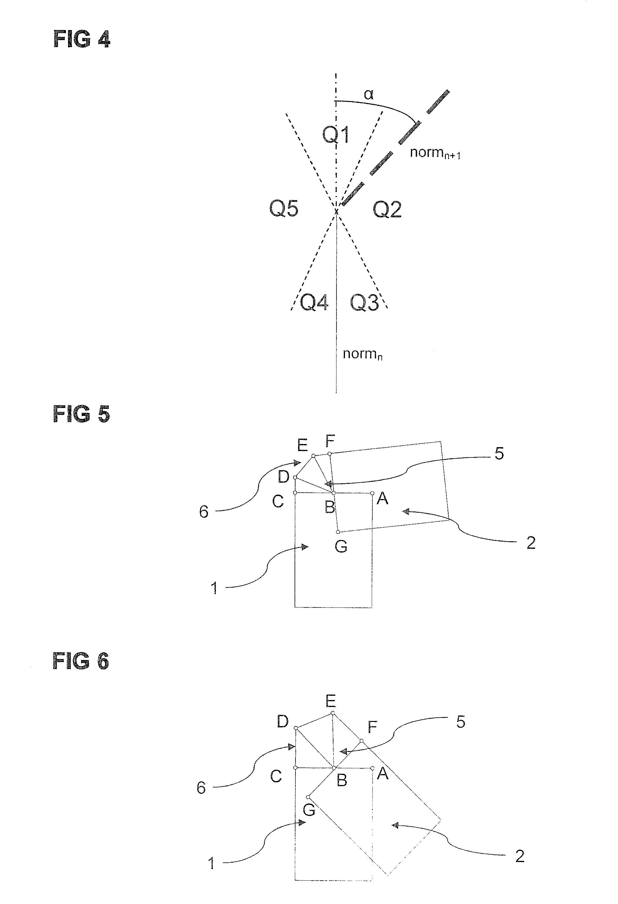
However, rectangle sequences such as these are subject to a problem with regard to the area between two successive rectangles, if the mutual alignment of the two successive rectangles differs noticeably, and is at an angle α. In this case, the two successive rectangles partially overlap while a visible gap remains on the side opposite the overlap area, which gap is not covered by either of the two successive rectangles.
A method such as this is highly computation intensive and, in particular, is unsuitable for displaying numerous continuous lines with a line width comprising a plurality of pixels.

Method used


Image

  • Method for displaying continuous lines
  • Method for displaying continuous lines
  • Method for displaying continuous lines

Examples


Embodiment Construction

[0033]It is known that a continuous line can be defined by a plurality of successive support points v1, v2 etc., and by a predetermined line width w. In order to display the continuous line on a display apparatus, for example on a display, it is expedient to display the continuous line by a sequence of rectangles connecting the respectively adjacent support points, with each rectangle in turn being composed of two triangles. In many graphics programming languages such as OpenGL, triangle sequences such as these can be produced and displayed particularly easily and quickly.

[0034]As can be seen from FIGS. 1 and 2, a normalized direction vector “dir” with the two components:

dir.x=(v1.x-v2.x)(v1.x-v2.x)2+(v1.y-v2.y)2(1)dir.y=(v1.y-v2.y)(v1.x-v2.x)2+(v1.y-v2.y)2(2)

and a normalized normal vector “norm” directed at right angles to the direction vector and having the components

norm·x=dir·y  (3)

norm·y=−dir·x  (4)

can be calculated for two successive support points v1 and v2 with the two-dimen...


PUM


Abstract

A method for displaying continuous lines on a raster-based display appliance, with a continuous line being defined by a sequence of two-dimensional support points v1 and v2 and a line width w, and with a rectangle 1, which connects the support points v1, v2, having a rectangle length predetermined by the distance between the support points v1, v2 and having a rectangle width predetermined by the line width w being displayed between two support points v1, v2. The method provides that a triangle sequence 6, which covers a gap 5 between the rectangles 1, 2, is displayed between two successive rectangles 1 and 2 whose alignment with respect to one another is at an angle α≧α0. The triangle sequence 6 includes a plurality of triangles which each have the support point v2, which connects the successive rectangles 1, 2, as a common corner point. A connecting triangle 7 is in each case displayed between the rectangle 1 and the triangle sequence 6 and between the triangle sequence 6 and the subsequent rectangle 2, the corner points of which connecting triangle 7 are the two corner points, which face the triangle sequence 6, of the rectangle 1, and of the subsequent rectangle 2 and the connecting support point v2. The corner points of the triangle sequence 6 are predetermined as a function of the angle α between the alignment of the successive rectangles 1, 2.

Description

BACKGROUND OF THE INVENTION[0001]1. Field of the Invention[0002]The invention relates to a method for displaying continuous lines on a raster-based display appliance, with a continuous line being defined by a sequence of two-dimensional support points and a line width, and with a rectangle, which connects each of the support points, having a rectangle length predetermined by the distance between the support points and having a rectangle width predetermined by the line width being displayed between two support points.[0003]Raster-based display appliances are used, for example, in vehicles or aircraft, and are used to display information which is important for operation and / or control of the vehicle or the aircraft. The respectively displayed information is intended to be displayed as clearly as possible, as well as quickly and in an unambiguously identifiable manner, on the display appliances that are used, normally screens or flat displays. At the same time, undesirable changes duri...

Claims


Application Information

Patent Timeline
Patent Type & Authority Applications(United States)
IPC IPC(8): G06T11/20
CPCG06T11/203
Inventor BADER, JOACHIMHOPPE, SVEN MARCO
Owner DIEHL AEROSPACE GMBH
Learn More