
Sports equipment hanger

a technology for sports equipment and hangers, applied in the field of sports equipment hangers, can solve the problems of difficult storage and drying, potential toppling, and easy toppling of prior art devices, and achieve the effect of convenient reconfigurability

Inactive Publication Date: 2010-05-20
MOREAU LESLIE WAYNE
View PDF33 Cites 24 Cited by
  • Summary
  • Abstract
  • Description
  • Claims
  • Application Information

AI Technical Summary

Benefits of technology

[0008]In a preferred embodiment, the present invention is directed to a portable sports equipment hanger which is easily reconfigurable.

Problems solved by technology

There are many sports which require a significant amount of equipment to protect a player when playing such sports, and such equipment varies in size, shape and weight and is typically difficult to store and dry in an organized manner such that a user may quickly and efficiently access and use the equipment.
Such prior art devices are easily toppled over, due to the fact that these devices typically rely on a truss base, which if loaded improperly, have the potential for toppling over.
Even if such devices are loaded properly they still have the potential of toppling over if bumped into by another object i.e. dog, child, adult etc. because the center of gravity of the loaded assembly is or could be too high with respect to its over turning moment not forgetting that the impact force will be coming from the top half of the assembly.
However the rack as contemplated by Klein et al is to be secured to a door or other vertical surface, is not able to retain sports equipment in an efficient configuration to assist in the drying and storage of such equipment and is not intended to be portable.
Both prior art references suffer from the same drawback in that the hanger is a unitary piece and does not accommodate multiple pieces of sports equipment.
For example, Kuhn generally discloses a unitary hanger on which pieces of equipment are to be hung from the free ends, and as illustrated, once the sports equipment is in place, appears to limit the amount of air movement between pieces thus significantly increasing the amount of time required to dry the equipment.

Method used


Image

  • Sports equipment hanger
  • Sports equipment hanger
  • Sports equipment hanger

Examples


Embodiment Construction

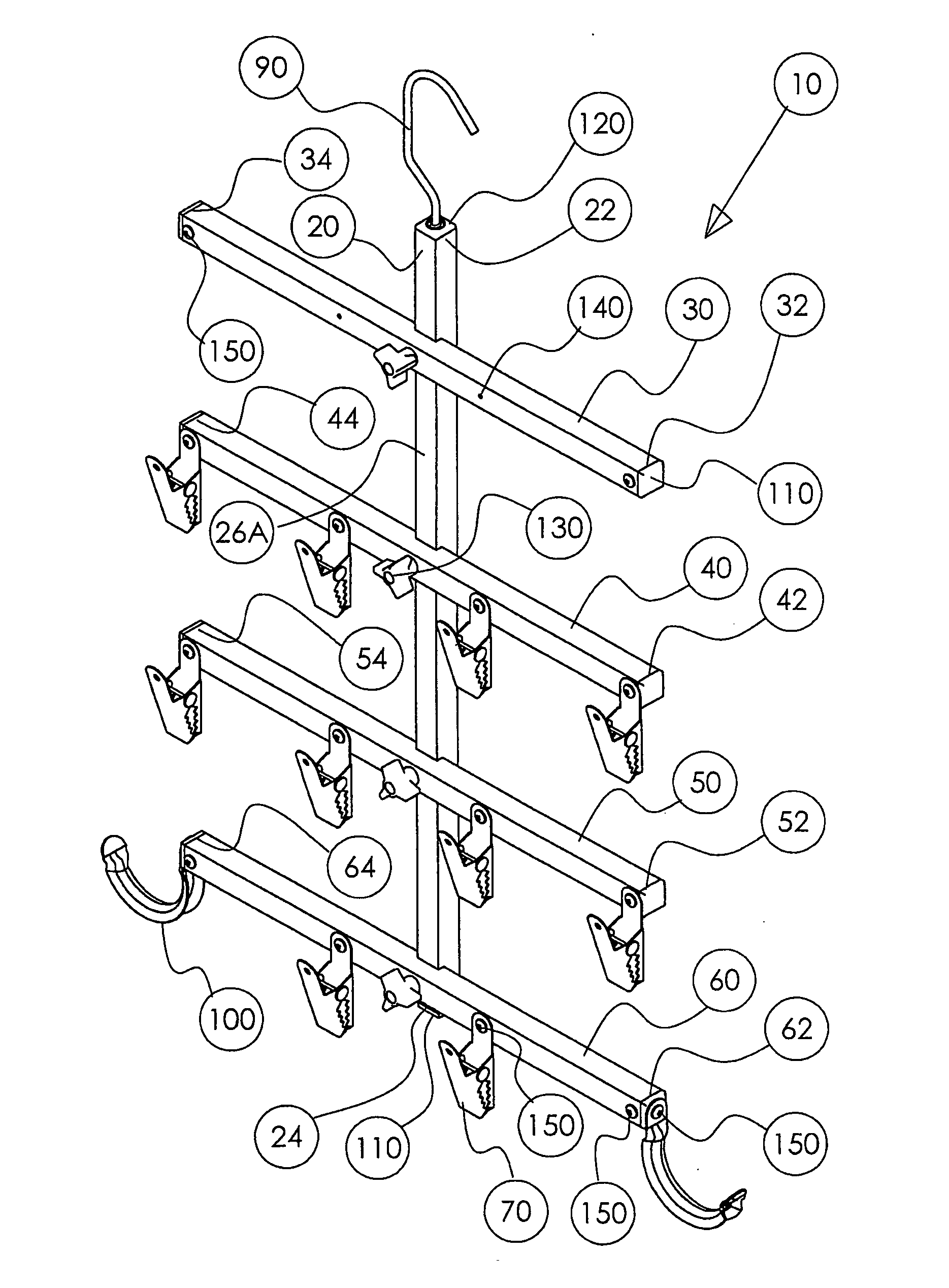
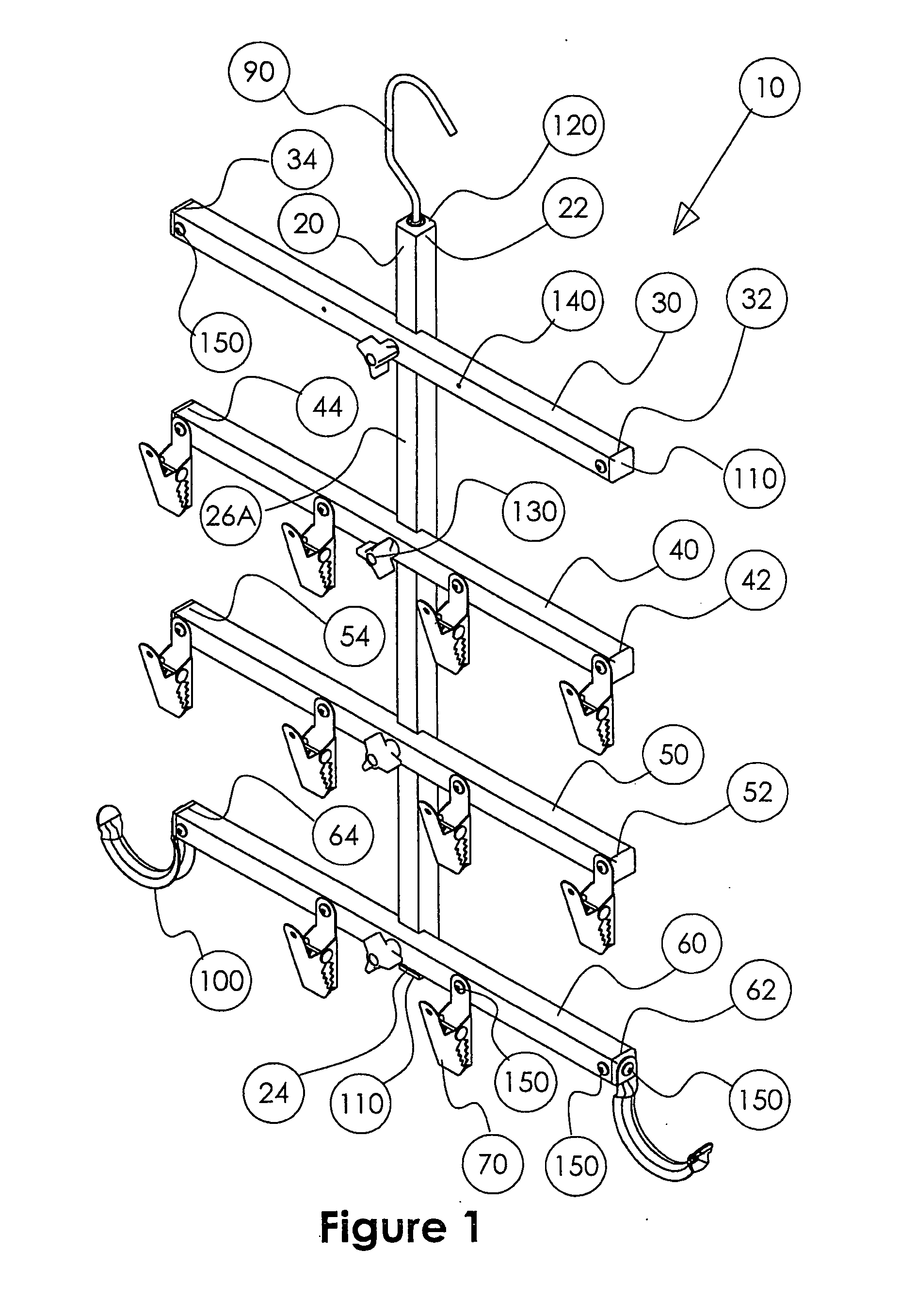
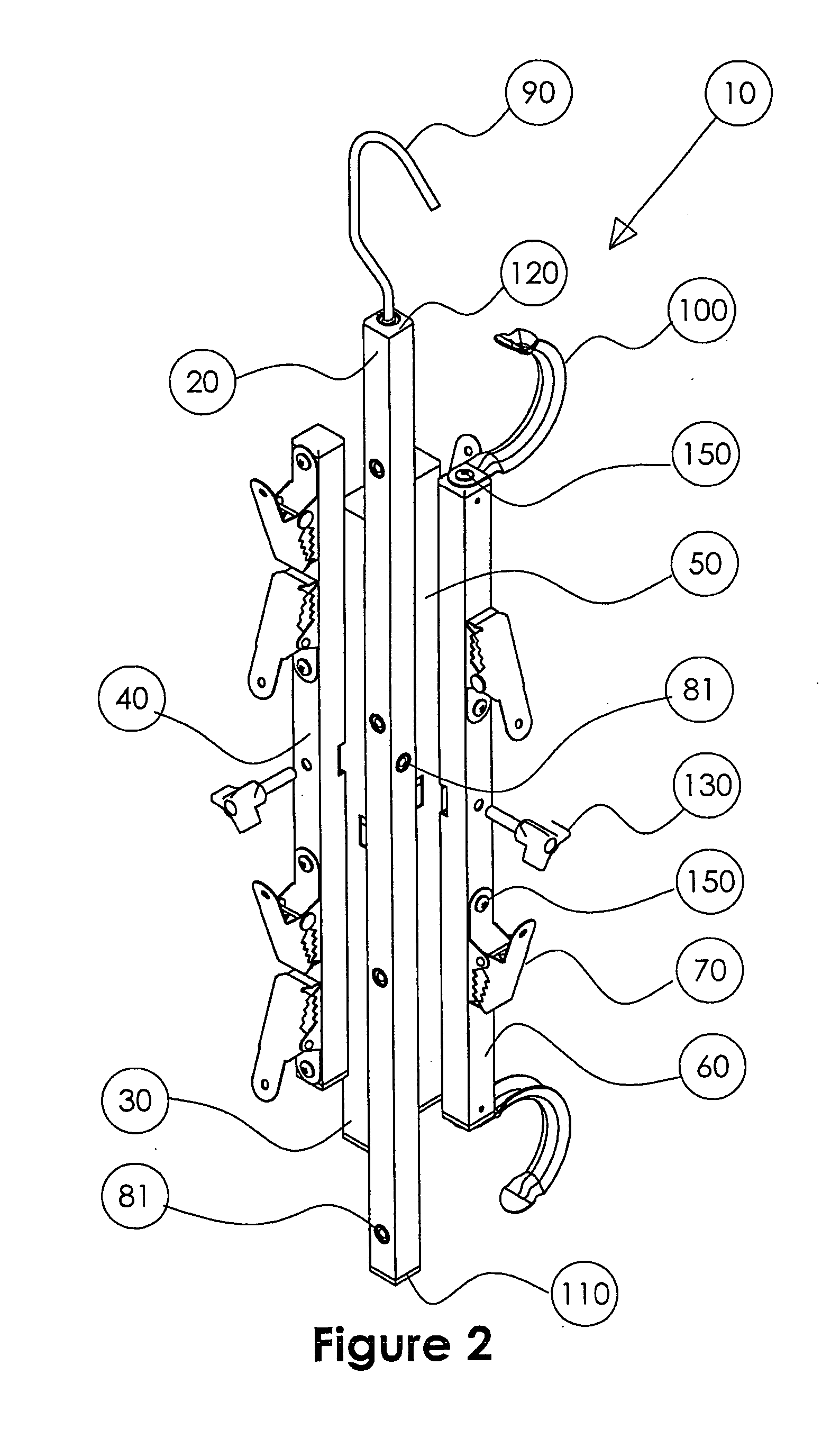
[0019]As illustrated in the accompanying drawing Figures, and in which like reference numerals denote like elements, there is provided a sports equipment hanger in accordance with the present invention generally designated by reference numeral 10.

[0020]The sports equipment hanger or gear hanger 10 includes a primary member 20 which, as illustrated in FIGS. 1 and 3, is in an operational condition in a generally vertical orientation. Primary vertical member 20 is an elongate tubular member having upper and lower opposed ends, 22 and 24, respectively.

[0021]A plurality of secondary equipment support members 30, 40, 50 and 60 are illustrated in a generally horizontal orientation with respect to the primary vertical member 20. As will be understood by those of skill in the art to which the present invention pertains, the apparatus is shown in an “in-use” orientation and the terms “vertical” and “horizontal” as used herein are used in accordance with the orientation as illustrated in the d...


PUM


Abstract

A portable, collapsible and reconfigurable hanger for hanging and drying sports equipment which comprises a primary frame member, a plurality of secondary frame members, each of the secondary frame members being adapted for releasable placement on the primary frame member in a substantially perpendicular orientation to the primary frame member; a plurality of sports equipment attachment means positioned on at least one of the secondary frame members for releasable engagement with an article of sports equipment, and releasable attachment means mounted on one end of the primary frame member for hanging the hanger in a generally vertical orientation when in use.

Description

FIELD OF THE INVENTION[0001]The present invention relates to an apparatus for drying and storing sports equipment, and more particularly to a portable and reconfigurable device for hanging and drying sports equipment thereon.BACKGROUND OF THE INVENTION[0002]The present invention relates to an apparatus for drying and storing equipment used for sports, such as hockey, North American football, lacrosse, etc. There are many sports which require a significant amount of equipment to protect a player when playing such sports, and such equipment varies in size, shape and weight and is typically difficult to store and dry in an organized manner such that a user may quickly and efficiently access and use the equipment.[0003]Typical of the prior art are stands or other floor mounted racks or structures placed upon the ground which have various appendages or supports adapted to receive different pieces of equipment. These devices take up space on the floor, such as in a closet, and require the...

Claims


Application Information

Patent Timeline
IPC IPC(8): A47F7/00
CPCA47G25/16D06F57/12A47G25/485A47G25/40
Inventor MOREAU, LESLIE WAYNE
Owner MOREAU LESLIE WAYNE
Learn More