
Industrial multilayer fabric having a narrowing weft

a multi-layer fabric and narrowing technology, applied in the field of industrial multi-layer fabrics, can solve the problems of reducing the strength of the joining portion which has been made endlessly, reducing the water retained by the wire, and deteriorating the rigidity of the fabric, so as to improve the rigidity, wear resistance, and dehydration the effect of property

Active Publication Date: 2010-05-13
NIPPON FILCON
View PDF25 Cites 7 Cited by
  • Summary
  • Abstract
  • Description
  • Claims
  • Application Information

AI Technical Summary

Benefits of technology

[0011]Since the number of lower side wefts is reduced and wefts have a long crimp structure, however, the number of confounding portions decreases. As a result, such fabrics have deteriorated rigidity and contain many undesirable movements of yarns. In addition to these problems, the strength of the joining portion which has been made endless decreases, because the diameter of constituent yarns is made smaller to thin the wire thickness and thereby reduce water retained by the wire or the number of confounding portions decreases.
[0012]An object of the present invention is to provide an industrial multilayer fabric excellent in rigidity, wear resistance, and joining strength when formed in an endless manner by arranging narrower wefts of a small diameter between lower side wefts so that a knuckle formed by lower side warps on the lower surface side is sandwiched between the narrower wefts.
[0013]The greatest characteristic of the industrial multilayer fabric of the present invention resides in that narrower wefts of a small diameter are arranged between lower side wefts so as to sandwich a knuckle formed by warps on the lower surface side. Since the narrower wefts are effective for improving the weaving strength of warps, they contribute to the formation of a fabric which does not expand easily and in addition, they have an excellent effect for improving size stability, running stability, and joining strength.

Problems solved by technology

As a result, such fabrics have deteriorated rigidity and contain many undesirable movements of yarns.
In addition to these problems, the strength of the joining portion which has been made endless decreases, because the diameter of constituent yarns is made smaller to thin the wire thickness and thereby reduce water retained by the wire or the number of confounding portions decreases.

Method used


Image

  • Industrial multilayer fabric having a narrowing weft
  • Industrial multilayer fabric having a narrowing weft
  • Industrial multilayer fabric having a narrowing weft

Examples


embodiment 1

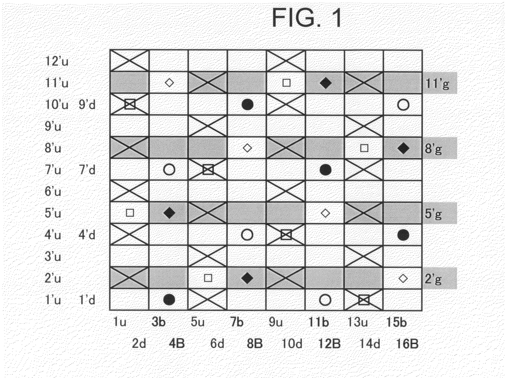
[0075]FIG. 1 is a design diagram of a double warp-double weft warp-binding structure according to Embodiment 1 of the present invention. In addition to upper side warps (u) and lower side warps (d), there are four pairs of a warp binding yarn (b) and a warp binding yarn (B). Narrower wefts are arranged alternately with lower side wefts and an arrangement ratio of upper side wefts to lower side wefts is 3:2.

[0076]As shown in the photograph of FIG. 13 illustrating the reverse side of the embodiment of the present invention, narrower wefts are placed between lower side wefts. The narrower wefts have a smaller diameter than lower side wefts and form a shorter crimp than that of lower side wefts on the lower side surface. According to this embodiment, lower side wefts each has a design in which it passes over two warps and then under six warps. narrower wefts each has a design in which it passes over one warp, under two warps, over one warp, and under four warps.

[0077]Narrower wefts form...

embodiment 2

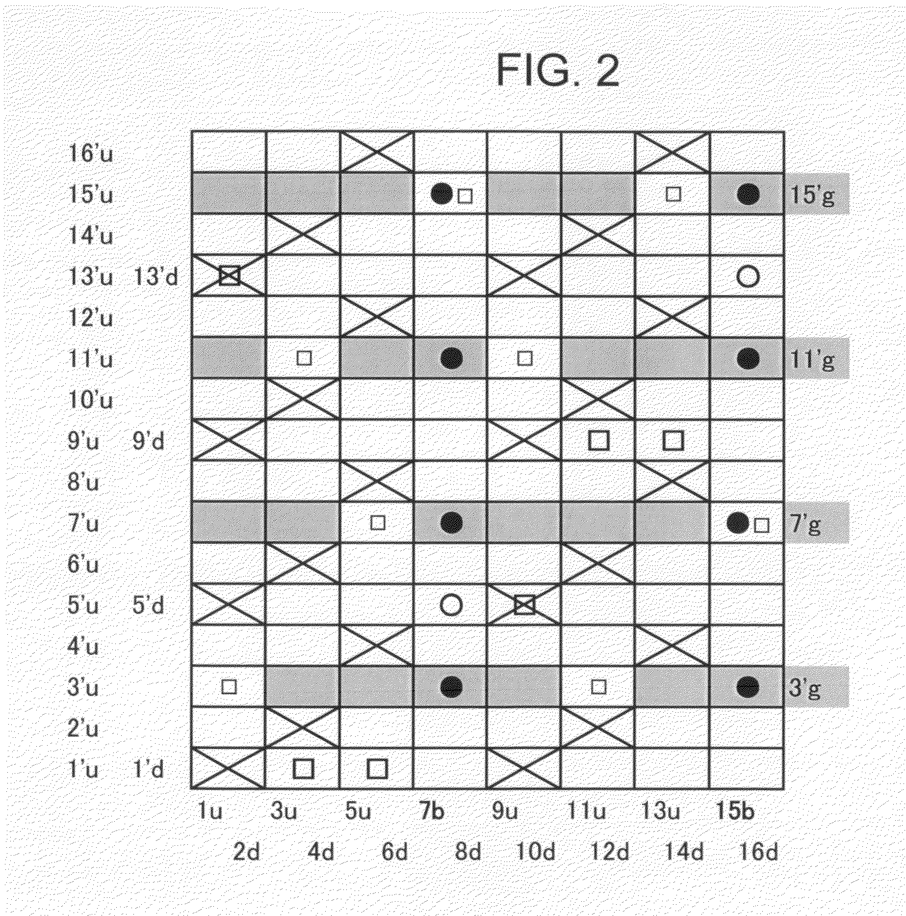
[0081]FIG. 2 is a design diagram of a fabric according to Embodiment 2 of the present invention. It is similar to the fabric of the above Embodiment and has a double warp-double weft warp-binding structure, but different in that a pair of warp binding yarns is composed of a warp binding yarn (b) and a lower side warp (d) and in an arrangement ratio, surface design, and an upper weft / lower weft ratio of 2:1. In Embodiment 1, a warp binding yarn is not involved in the formation of a surface design, while in the present embodiment, a warp binding yarn has both a function of a binding yarn and a function of an upper side warp. Upper side warps and warp binding yarns are woven with upper side wefts to form a sateen weave design.

[0082]Narrower wefts form, at a knuckle portion “∘” formed by a lower side warp passing under a lower side weft, crimps on the lower side surface (shaded portions) so as to sandwich the knuckle from both sides. This enables to form a fabric having improved rigidit...

embodiment 3

[0083]FIG. 3 is a design diagram of a fabric according to Embodiment 3 of the present invention. It is different from Embodiment 1 in the arrangement of warp binding yarns. The fabric of this embodiment has a pair of two warp binding yarns (b, B) and a pair of an upper side warp (u) and a warp binding yarn (B). Lower side wefts each passes over one warp (“∘” or “□”) to form a knuckle portion and then passes under seven warps to form a long crimp. Narrower wefts each repeats a design in which it passes over one warp and then passes under three warps to form a crimp which is shorter than that of the lower side wefts to sandwich the knuckle portion.


PUM

PropertyMeasurementUnit
diameteraaaaaaaaaa
diameteraaaaaaaaaa
diameteraaaaaaaaaa

Abstract

In an industrial multilayer fabric, narrower wefts of a small diameter are placed between lower side wefts so as to sandwich a knuckle formed by a lower side warp on the lower surface side of the fabric.The industrial fabric is obtained by stacking at least upper side wefts and lower side wefts one after another and weaving these wefts with warps, wherein narrower wefts having a smaller diameter than that of the lower side wefts and forming a shorter crimp than that formed by the lower side wefts on the lower side surface are arranged between the lower side wefts; and at a knuckle portion formed by warps passing under one or two successive lower side wefts, the narrower wefts form a crimp passing under lower side warps so as to sandwich, from both sides, one knuckle or two knuckles formed by two adjacent warps under two adjacent wefts.

Description

CROSS-REFERENCES TO RELATED APPLICATION[0001]This application claims priority from Japanese Patent Application Serial No. 2008-289440 filed Nov. 12, 2008, the contents of which are incorporated herein by reference in its entirety.BACKGROUND OF THE INVENTION[0002]1. Field of the Invention[0003]The present invention relates to industrial multilayer fabrics having improved rigidity and wear resistance and also having improved strength at a joining portion where yarns are joined in an endless manner by weaving. Such advantages are actualized by employing a structure in which narrower wefts of a small diameter are arranged between lower side wefts so as to sandwich therebetween a knuckle formed by warps on the lower surface side.[0004]2. Description of the Related Art[0005]Fabrics formed by weaving warps and wefts have heretofore been used widely as an industrial fabric, for example, papermaking fabrics, conveying belts, and filter cloths. They are required to have fabric properties suit...

Claims


Application Information

Patent Timeline
Patent Type & Authority Applications(United States)
IPC IPC(8): D03D15/00B32B3/10
CPCY10T428/2481D21F1/0036Y10T442/3065
Inventor UEDA, IKUOKONDO, YOSHIHISA
Owner NIPPON FILCON
Learn More