Airborne stabilized wind turbines system

a wind turbine and stabilizer technology, applied in the field of wind turbine systems, can solve the problems of limited land for building the towers to support such wind turbines, high construction cost, and high vibration, and achieve the effects of accurate and complicated angular controller, low cost, and simple and reliable way

Inactive Publication Date: 2010-05-13
MELLER MOSHE
View PDF49 Cites 15 Cited by
  • Summary
  • Abstract
  • Description
  • Claims
  • Application Information

AI Technical Summary

Benefits of technology

[0026]In another version of the invention, the turbine section will include more than one wind turbine, these turbines are constructed in a way that when the wind is blowing through them they will rotate in opposite directions; therefore each one of the turbines will induce rotational torque on the system in opposite directions. These opposite rotational torques will balance each other; but in order to avoid the rotating of the whole system the result of the torques acting on the system, must be zero, achieving zero torques result, requires a very accurate and complicated angular controller. This angular controller should continuously control the angle of attack of the wind turbines blades, the power that produced by the generators of the system and other things that can influence the magnitude of the torque that each turbine inducing on the system. The alternative to this complicated angular controller is system that utilizing the principle of the present invention in the same way as described above. The only different in this type of system with more than one wind turbine, is that the required returning torque RT needs to balance only the differential unbalanced torque that has not been balanced by the opposite rotating turbines. And, this can be achieved in low cost and in simple and reliable way, using the principle of the present invention.

Problems solved by technology

However, tall towers are expensive to build and once built, are subject to intense vibrations during operation.
Furthermore, land for building the towers to support such wind turbines is limited in view of numerous, known factors, including acquisition costs, environmental impact, zoning issues.
Although offshore winds, i.e., winds over bodies of water, are stronger than winds over land, the construction of support structures for wind turbines over a body of water is expensive, although there are significantly fewer limitations on the space for building support structures over such bodies of water.
The most notable limitation is that the construction of support structures for wind turbines is limited to certain depths of the bodies of water.
A drawback of this prior art system is that its power generation is very limited and it is not very efficient.
Among its drawbacks are that it is expensive to construct, includes complex mechanical parts and is not very practical.

Method used


Image

  • Airborne stabilized wind turbines  system
  • Airborne stabilized wind turbines  system
  • Airborne stabilized wind turbines  system

Examples


second embodiment

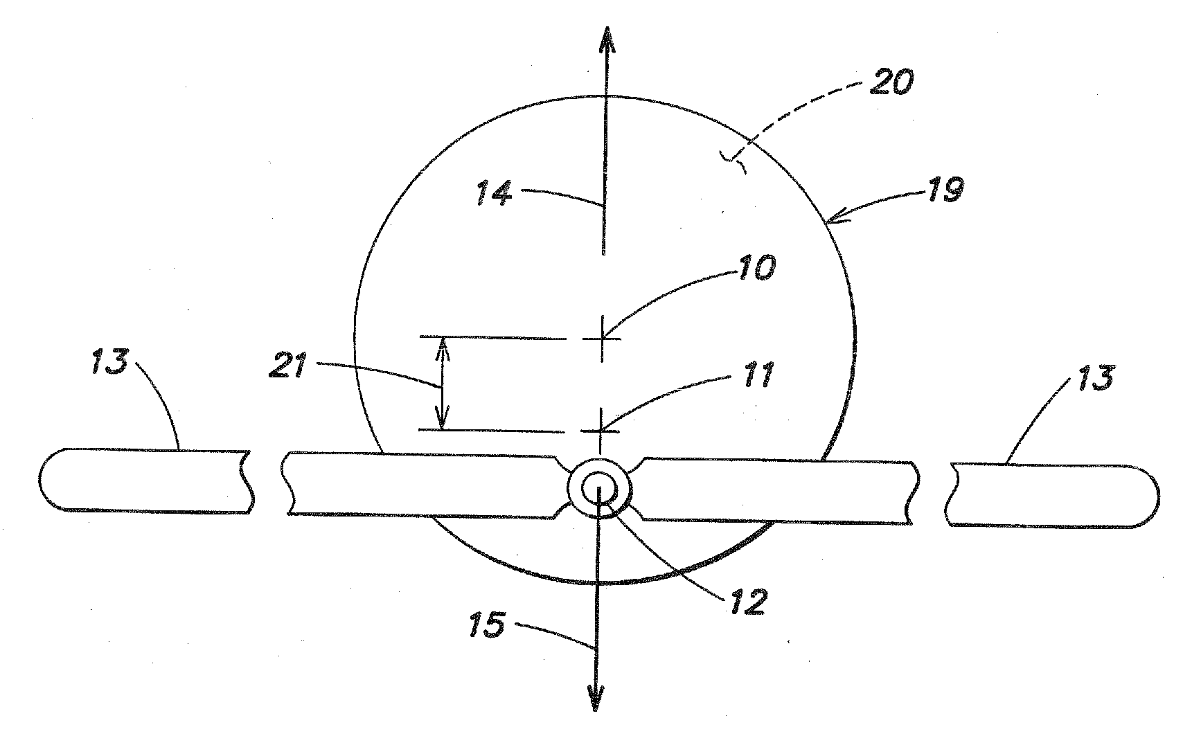
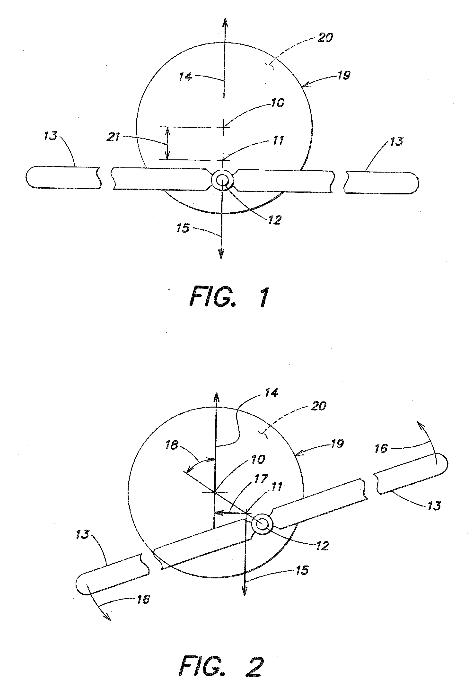
[0058]In this second embodiment of the invention, the wind turbine section includes at least one wind turbine, but can include a few wind turbines wherein part of them will rotate in the opposite direction from the rest. The turbine section of this embodiment is connected by a tether to the lifting section, and by another tether to the anchoring section.

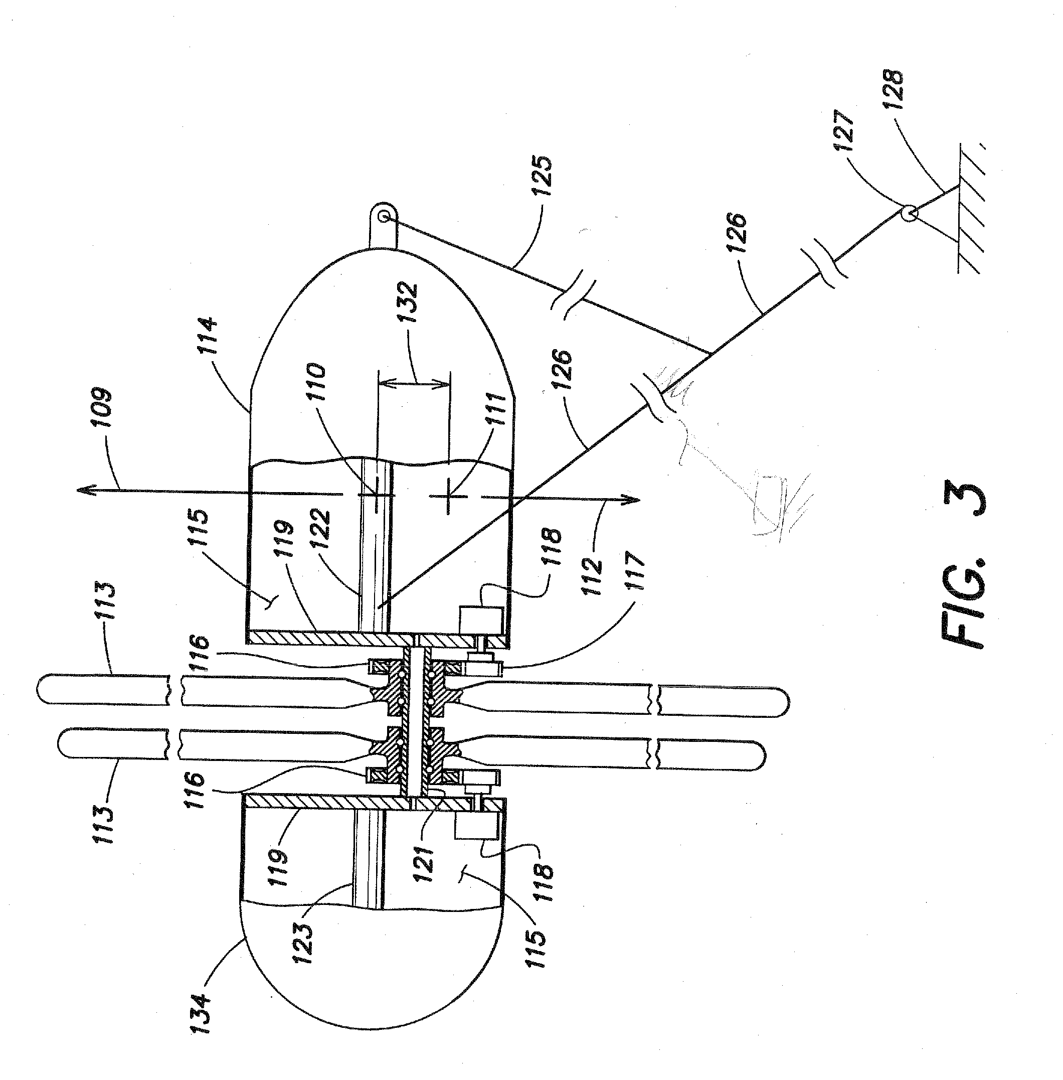
[0059]The lifting section: 214 is a lifting body that is filled with lighter than air gas 215, like helium, hydrogen, hot air or any other lighter than air gas. The lifting body 214 has an aerodynamic shape so when the wind 240 is blowing over the lifting body 214, there is an additional lifting force acting on the lifting body 214. The lifting body 214 is connected to the turbine section of the system through a tether 225.

[0060]In the turbine section, 221 is the main shaft, this is preferably a cylindrical hollow tube that gives a constructional strength to the turbine section; it is made preferably from composite material or from o...

third embodiment

[0080]FIG. 10 is a side view partly cross section of the present invention.

[0081]In this embodiment, there are a plurality of turbines sections that are connected by tether 226 in a serial formation. The upper turbines section is connected to the lifting section, and lower turbines section is connected to the anchoring base 228 preferably through winch 227 that can control the operational altitude of the plurality of turbine sections.

[0082]Each turbine section, the lifting section, and the anchoring base are similar to those shown in FIGS. 6-8.

[0083]The advantages of this embodiment are: harvesting of wind energy in multiples altitudes by the same system; the cost of electricity output will be lower.

[0084]The disadvantage is: the system is more complicate to control and to maintain.

[0085]FIG. 11 shows a possible lifting section that can generate the lifting force to the airborne system, in different embodiments of the invention.

[0086]Element 327 is an air foil lifter kite; 314 are i...


PUM


Abstract

Airborne system for producing electricity from wind includes at least one shaft, one or more wind turbines rotatably mounted to each shaft, and generators that convert rotation of the turbine(s) into electricity. A lifting section is connected to the shaft(s) and generates a lifting force that causes the system to be airborne. A center of gravity of the system is lower than its center of lift. When the turbines are exposed to wind and rotate (at least one in one direction and another in an opposite direction), torques induced on the shaft(s) of the system balance each other and remaining deferential torque is balanced by returning torque that is generated by the angular deviation of the center of gravity from its lowest position. A magnitude of this returning torque increases as the angular deviation increases until the system reach angular stability. Electricity is generated and conducted for storage or usage.

Description

CROSS-REFERENCE TO RELATED APPLICATIONS[0001]The present application is a continuation-in-part of U.S. patent application Ser. No. 12 / 284,046 filed Sep. 18, 2008, and is related to U.S. patent application Ser. No. 12 / 465,877 filed May 14, 2009 which is a divisional of the '046 application, both of which are incorporated herein by reference.FIELD OF THE INVENTION[0002]The present invention relates generally to a wind turbine system for generating electricity and more specifically to a wind turbine system for generating electricity which is airborne, and includes both turbine and generator on a common, airborne structure.BACKGROUND OF THE INVENTION[0003]Wind energy is one of the most readily available forms of renewable energy, which include solar, hydro, geothermal energy, and is therefore often used to generate electricity. The density of wind energy, in terms of watts per square meter, is one of the highest among other forms of renewable energy.[0004]Existing systems for utilizing ...

Claims


Application Information

Patent Timeline
Patent Type & Authority Applications(United States)
IPC IPC(8): F03D9/00F03D5/00H02K7/18
CPCF05B2240/922Y02E10/70Y02E10/725F05B2240/921F03D1/025F03D5/00F05B2240/917Y02E10/728F03D9/11F03D9/25F03D13/20Y02E10/72Y02E70/30
Inventor MELLER, MOSHE
Owner MELLER MOSHE
Why Eureka
Try Eureka