
Magnetic carrier, two component developer, developing device, image forming apparatus, and image forming method

a technology of magnetic carrier and developing device, which is applied in the direction of electrophotographic equipment, instruments, developers, etc., can solve the problems of deteriorating charging property of carrier, electric charge of electrophotographic toner, and electric resistance likely to decrease, so as to prevent or inhibit photographic fog and cause no deterioration of charging property of toner

Inactive Publication Date: 2010-04-29
SHARP KK
View PDF12 Cites 0 Cited by
  • Summary
  • Abstract
  • Description
  • Claims
  • Application Information

AI Technical Summary

Benefits of technology

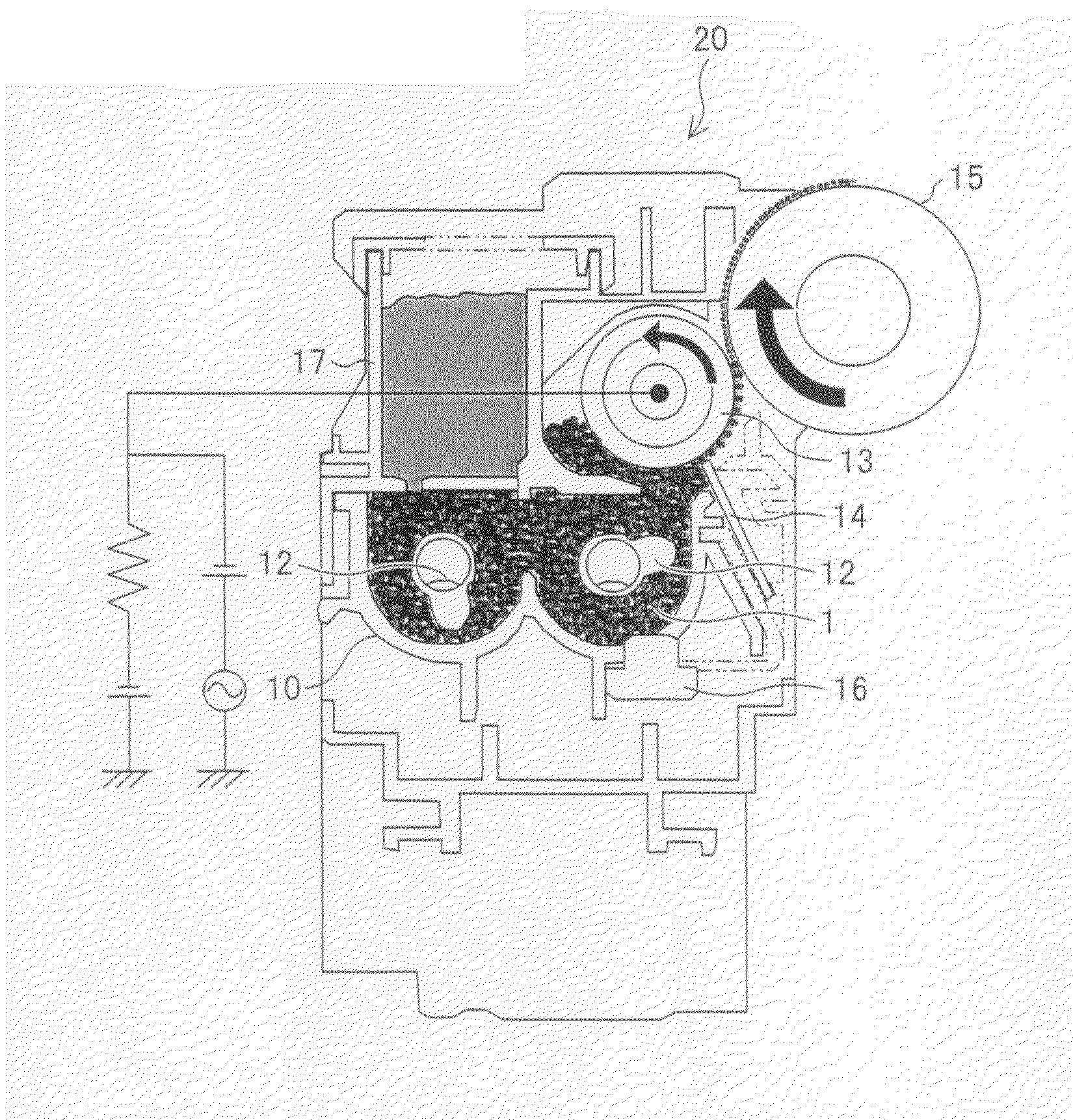
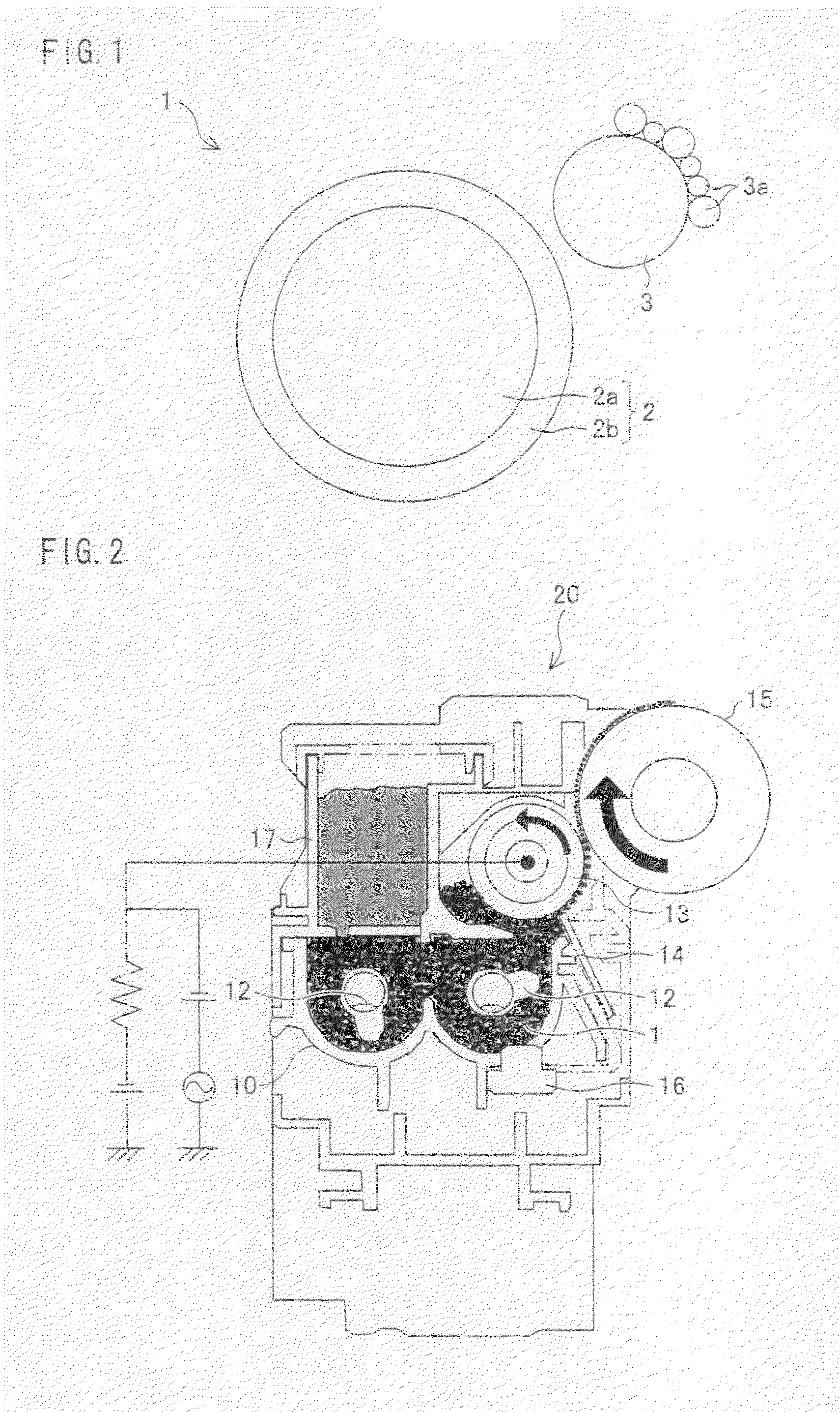
[0013]The present invention has been made in view of the foregoing problems, and an object of the present invention is to achieve a carrier for electrostatic latent image development and a two component developer each of which is free from the foregoing problems. Specifically, an object of the present invention is to achieve a magnetic carrier, a two component developer, a developing device, an image forming apparatus, and an image forming method each of which causes no adherence of a carrier to a surface of an image bearing member, prevents or inhibits photographic fog, and causes no deterioration in a charging property of a toner even over a long period of time.
[0016]With this configuration, adherence of the carrier to an image section and a non-image section is significantly reduced, and no image deterioration such as white spots which are produced during a transfer occurs in the image section. Further, in the non-image section, no image defect in a form of a streak occurs, because a surface of a cleaning blade and a surface of an electrostatic latent image bearing member are not damaged. As such, it is possible to achieve a high-quality image. Furthermore, since the charging property of the electrophotographic toner is improved and therefore a larger proportion of the electrophotographic toner has a stable charge, photographic fog does not occur in a background area when a density of an image is high. As a result, it is possible to achieve an image having an excellent quality over a long period of time.

Problems solved by technology

However, in a part where the resin coating layer is thin, a spent of the partially-coated carrier due to an electrophotographic toner that is finely powdered is likely to occur, thereby deteriorating a charging property of the carrier.
Further, since an electric resistance is likely to decrease in a part where the resin coating layer is thin, electric charge of the electrophotographic toner that once reached a desired charge amount leaks via a low-resistance part of the surface of the carrier.
This causes scattering of the toner and / or photographic fog.
This is a cause of a fatal defect in an image.
However, since this carrier has a two-phased coating that is obtained by filling resin containing an electrically conductive material into the recessed parts of the magnetic core particles and then additionally coating the surfaces of the carrier particles with the resin layer, cost increase occurs.
This causes photographic fog and / or scattering.
However, the problems have not yet been solved.

Method used


Image

  • Magnetic carrier, two component developer, developing device, image forming apparatus, and image forming method
  • Magnetic carrier, two component developer, developing device, image forming apparatus, and image forming method
  • Magnetic carrier, two component developer, developing device, image forming apparatus, and image forming method

Examples


example 1

[0107]Resin-coated carriers were produced according to the method described in the (Production of Resin-Coated Carrier), but by using respective coating resin solutions containing the electrically conductive particles in respective amounts of 0 parts by weight, 5 parts by weight, 10 parts by weight, 15 parts by weight, and 20 parts by weight. Then, a resistance value of each of the resin-coated carriers was measured according to the method described in the (Measurement of Resistance Value of Carrier Particles).

[0108]Further, two component developers were produced by using (i) a cyan evaluation toner produced according to the method described in the (Production of Toner) and (ii) the respective resin-coated carriers each containing a different amount of the electrically conductive fine particles (each having a different resistance). Thereafter, each of the two component developers was supplied into the developing cartridge A. The developing cartridge A was then set in the test bench ...

example 2

[0118]Magnetic core particles each having a different resistance value were prepared, and the electric resistance values were measured according to the (Measurement of Resistance Value of Magnetic Core Particles). Further, resin-coated carriers were produced in such a manner that surfaces of the magnetic core particles each having a different resistance value were coated with resin according to the method described in the (Production of Resin-Coated Carrier).

[0119]Further, two component developers were produced by using (i) a cyan evaluation toner produced according to the method described in the (Production of Toner) and (ii) the respective resin-coated carriers each having a different resistance. Thereafter, each of the two component developers was supplied into the developing cartridge A. The developing cartridge A was set in the test bench described in the (Evaluation of Adherence of Carrier and Photographic Fog in Background Area). Then, after idling of the test bench for 3 min...

example 3

[0122]Magnetic core particles each having a different volume average particle size were prepared and coated with resin according to the method described in the (Production of Resin-Coated Carrier), so that resin-coated carriers were produced. Then, evaluation was carried out on the resin-coated carriers employing the magnetic core particles each having the different volume average particle size, according to the (Evaluation of Adherence of Carrier and Photographic Fog in Background). Table 3 shows results of the evaluation.

TABLE 3VolumeAverageAdherenceParticle SizeofPhotographic(μm)CarrierFogExample 320POORFAIR35FAIRGOOD45EXCELLENTEXCELLENT55EXCELLENTEXCELLENT90EXCELLENTGOOD

[0123]Table 3 shows that in a case where the volume average particle size of the resin-coated carrier is 20 μm or less, each of the resin-coated carriers is caused to easily adhere to the surface of the electrostatic latent image bearing member because a holding power of a magnetic roller incorporated in the deve...


PUM


Abstract

Regarding a magnetic carrier of the present invention, a surface of a magnetic core material is coated with a coating layer containing electrically conductive particles and a charge control agent composed of same components as components of a charge control agent contained in a electrophotographic toner. Further, the magnetic carrier exhibits an electric resistance value of 8.22×10⁷ Ωcm to 1.12×10¹⁰ Ωcm in an electric field of 4×10³ V / cm. This allows the magnetic carrier to stay capable of charging the electrophotographic toner even over a long period of time.

Description

TECHNICAL FIELD [0001]The present invention relates to (i) a magnetic carrier used for development of an electrostatic latent image pattern in an image forming method employing an electrophotographic printing method, (ii) a two component developer containing the magnetic carrier and a toner, (iii) an image forming apparatus employing the two component developer, and (iv) an image forming method employing the two component developer.BACKGROUND ART [0002]An image forming apparatus employing an electrophotographic printing method has been widely used as a copier, a printer, a facsimile, and the like. The image forming apparatus employing the electrophotographic printing method forms an image on recording paper through a charging step, an exposing step, a developing step, a transferring step, a cleaning step, and a fixing step. Here, the image forming apparatus employs a developer, which is (i) an electrophotographic two component developer composed of a toner for development of an elec...

Claims


Application Information

Patent Timeline
IPC IPC(8): G03G15/09
CPCG03G9/0819G03G9/107G03G9/1131G03G2215/0607G03G9/1139G03G15/09G03G9/1136
Inventor YOSHIOKA, NOBUYUKIIWAMATSU, TADASHIMUTUO, YOSHINORIHIRAKAWA, HIROYUKIHARA, TAKASHIKAMOTO, TAKANORI
Owner SHARP KK
Learn More