
Hydrogel-based tactile-feedback touch screen

a touch screen and hydrogel technology, applied in the field of touch screen displays, can solve the problems of lack of positive tactile feedback, intimidation of unfamiliar users of computers by input devices, and implementation of screen interfaces

Inactive Publication Date: 2010-04-22
HONEYWELL INT INC
View PDF2 Cites 82 Cited by
  • Summary
  • Abstract
  • Description
  • Claims
  • Application Information

AI Technical Summary

Benefits of technology

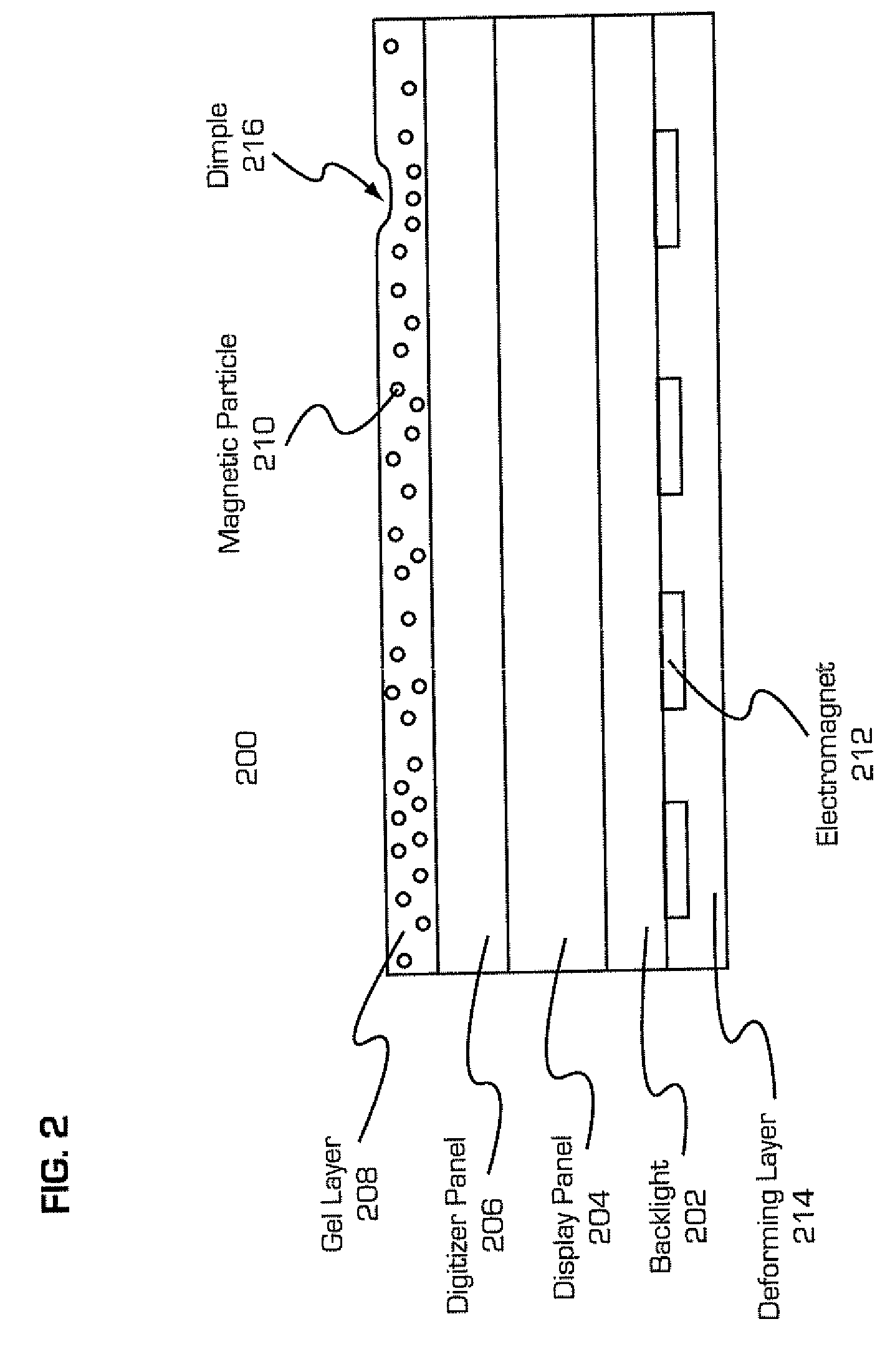
The present invention is related to a touch-screen display with a gel layer that can detect user touch and provide feedback through deformation. The gel layer has a honeycomb structure with cells containing hydrogel and electrodes. The electrodes are arranged in two matrices, one on the top and one on the bottom of the gel layer. The electrodes are vertically aligned with individual cells. The invention also includes a controller for controlling the deformation of the gel layer. The technical effect of this invention is to provide a more immersive user experience through touch and feedback on a touch-screen display.

Problems solved by technology

Often times people unfamiliar with computers become intimidated with input devices such as mice and trackpads.
However, a significant disadvantage of touch-screen implemented interfaces is the lack of positive tactile feedback.
For example, it is impossible to operate a “soft” keyboard while doing something else (such as flying an aircraft), because there is no way to feel where the keys are positioned.
Similarly, it can be difficult for visually impaired people to operate such devices, as there is no means of providing Braille identification on the keycaps or other interface elements.
However, the disclosed lid is limited to being utilized for only one particular arrangement of interface elements.
Consequently, the touch screen display would not be capable of providing dynamic placement of interface elements based on the requirements of different applications being executed or functions being performed.
Moreover, rapid typing can be difficult on a touch-screen keyboard since the typist does not receive any feedback when a key is pressed on the screen.

Method used


Image

  • Hydrogel-based tactile-feedback touch screen
  • Hydrogel-based tactile-feedback touch screen
  • Hydrogel-based tactile-feedback touch screen

Examples


Embodiment Construction

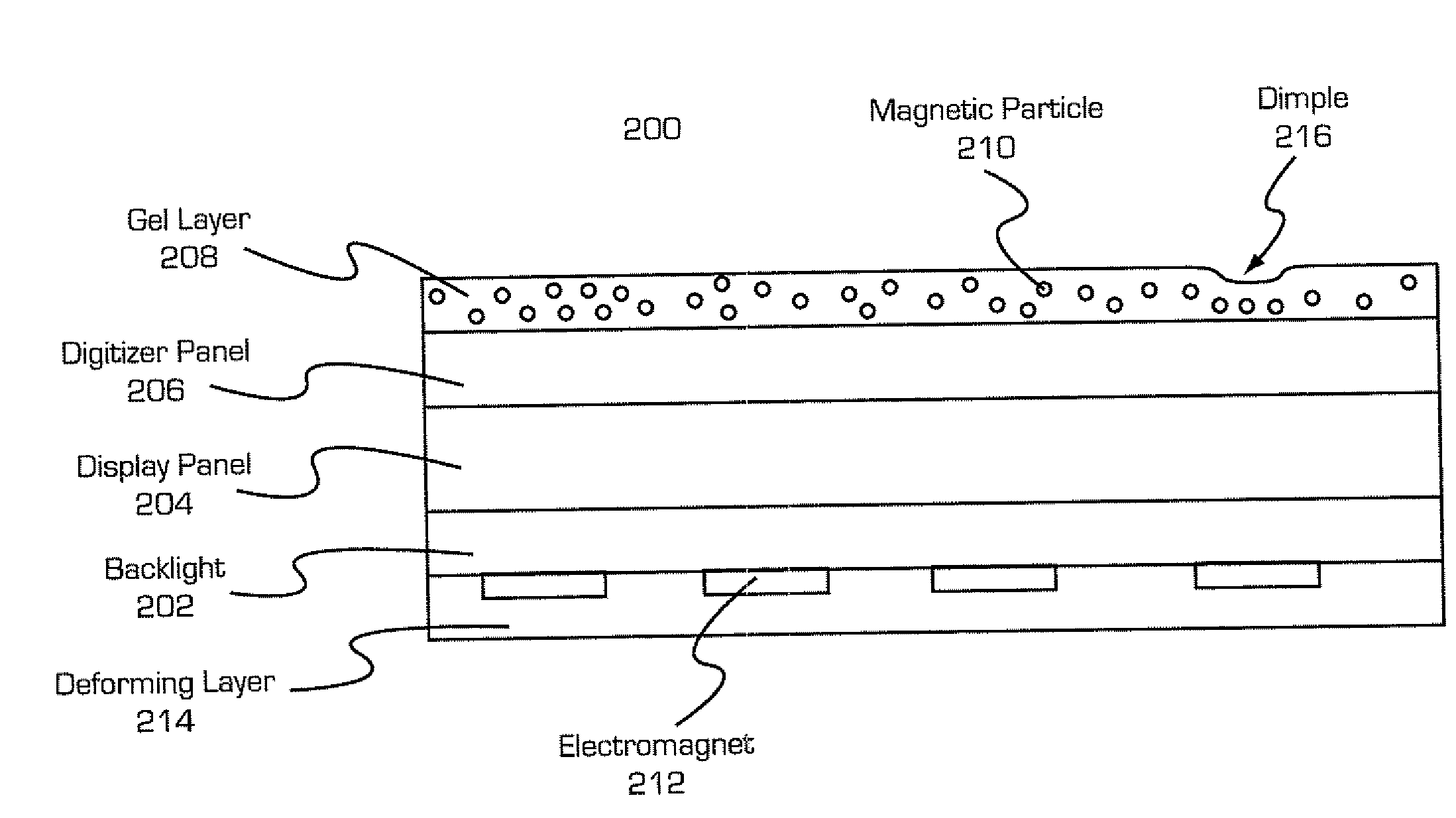
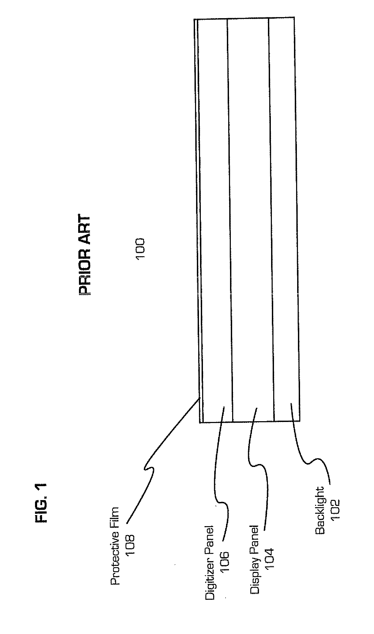
[0020]A conventional touch-screen display 100, either LCD-based or LED-based, are constructed of several subassemblies, each of which have several component layers. The subassemblies are a backlight 102 (only used in LCD-based displays), display panel 104 and a digitizer panel 106 stacked from back to front respectively. In addition, a protective film 108 is disposed on the top surface of the conventional touch-screen display 100.

[0021]The backlight 102 provides illumination for transmissive-type LCD display panels. Alternatively, when the display panel 104 is a reflective-type LCD display panels, instead a reflector that reflects ambient light, such as sunlight or room lighting, replaces the backlight 102. In the case where the display panel 104 is an LED display, neither a reflector nor a backlight is required since the individual pixel elements of the LED display emit their own light.

[0022]As mentioned above, the display panel 104 may be either LCD-based or LED-based. An LCD disp...


PUM


Abstract

A system and method for providing tactile feedback on a touch screen display unit is provided. The tactile feedback unit has a gel layer for deforming discrete surface areas of a touch-screen display; and a tactile feedback controller for controlling the deformation by the gel layer. The tactile feedback unit is overlaid onto a liquid crystal display, OLED display, or other types of touch screen displays. Areas of the gel layer are individually controllable by the tactile feedback controller, such that areas of the gel layer that overlay control elements of a graphical user interface displayed on the touch screen display are activated. Additionally, contact with the touch screen display by a user at an area defined as a control element causes the corresponding area of the gel layer to provide a tactile feedback, such as deformation, vibration, etc.

Description

I. CROSS REFERENCE[0001]The present invention is related to co-pending application entitled “Tactile-Feedback Touch Screen” and having the inventors of the present invention in common.II. FIELD OF THE INVENTION[0002]The present invention relates generally to touch screen displays, and more specifically, the present invention relates to a system and method for providing tactile feedback on a touch screen.III. BACKGROUND OF THE DISCLOSURE[0003]Often times people unfamiliar with computers become intimidated with input devices such as mice and trackpads. Recent innovations such as the Apple iPhone have increased public awareness of, and desire for, touch-screen-controlled applications. Touch-screen interfaces provide the user with a more intuitive way of controlling a computer or electronic appliance.[0004]Moreover, a touch-screen allows programmers to provide customized interfaces, which may be more appropriate for particular applications. Such as slider elements, buttons, dials and ke...

Claims


Application Information

Patent Timeline
Patent Type & Authority Applications(United States)
IPC IPC(8): G06F3/041
CPCG06F3/041G06F3/016G06F3/04886G06F2203/04809
Inventor EDWARDS, LEWINMCCRIMMON, PATRICIAWATSON, RICHARD THOMAS
Owner HONEYWELL INT INC
Learn More