
Needle-electrode and tissue anchor system

a tissue anchor and electro-electrode technology, applied in the field of medical procedures, can solve the problems of inability to use such known instruments for tissue approximation and retraction, inconvenient use, and inconvenient use, so as to improve the cost, time or the ability, and the effect of better anchoring

Active Publication Date: 2010-04-15
BOARD OF RGT THE UNIV OF TEXAS SYST
View PDF15 Cites 101 Cited by
  • Summary
  • Abstract
  • Description
  • Claims
  • Application Information

AI Technical Summary

Benefits of technology

[0013]In this field, special and sometimes simple devices from the viewpoint of hindsight can yield major improvements in costs, time, or the ability to even perform a desired medical procedure. The present disclosure provides an improved method and device for better inserting of an anchor into a tissue portion for approximation and retraction of a tissue portion during a medical procedure.

Problems solved by technology

The gap between adjacent sides of the wound may be so large as to make the closure tenuous and time consuming.
However, the current endoscopic, laparoscopic, and other medical procedures performed internally to the body create an order of magnitude in complexity.
The limited viewing and access during these internal procedures typically prohibit the use of such known instruments for tissue approximation and retraction.
The size of the typical instruments is prohibitive for the internal procedures, but more importantly most procedures need to be done with one instrument inserted into the area.
However, a gap that exceeds the capabilities of the clips needs special and time consuming efforts to close.
However, inserting the anchor through the wall can be technically challenging due to the thickness of some portions of the wall.
A significant amount of force is needed to push the needle and anchor through the wall and often bends the flexible endoscope or other scope through which the needle is inserted.
The amount of force complicates the procedure and at time requires placement of the anchor to a less desirable location.

Method used


Image

  • Needle-electrode and tissue anchor system
  • Needle-electrode and tissue anchor system
  • Needle-electrode and tissue anchor system

Examples


Embodiment Construction

[0035]One or more illustrative embodiments of the concepts disclosed herein are presented below. Not all features of an actual implementation are described or shown in this application for the sake of clarity. It is understood that the development of an actual embodiment, numerous implementation-specific decisions must be made to achieve the developer's goals, such as compliance with system-related, business-related and other constraints, which vary by implementation and from time to time. While a developer's efforts might be complex and time-consuming, such efforts would be, nevertheless, a routine undertaking for those of ordinary skill in the art having benefit of this disclosure.

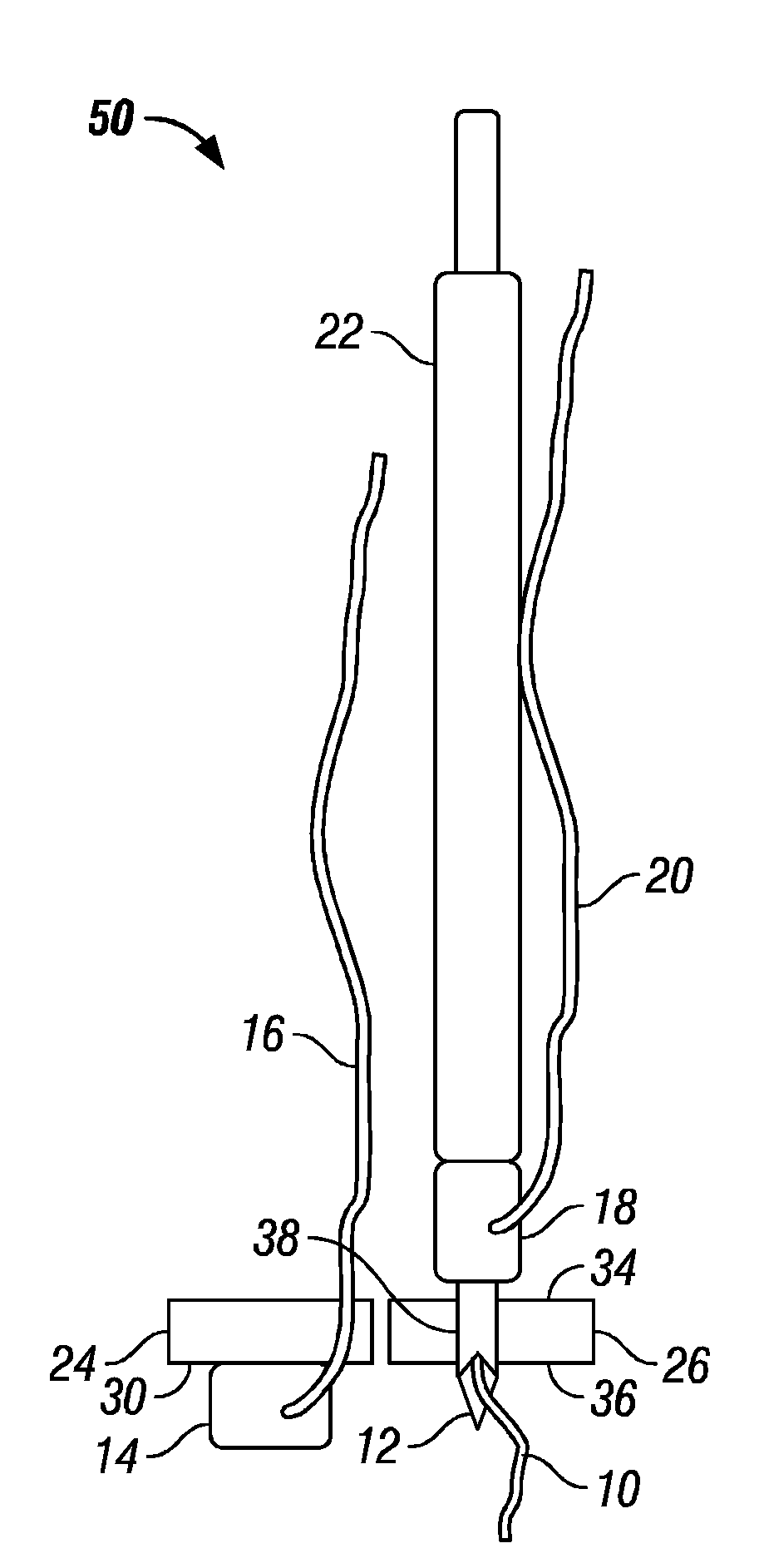
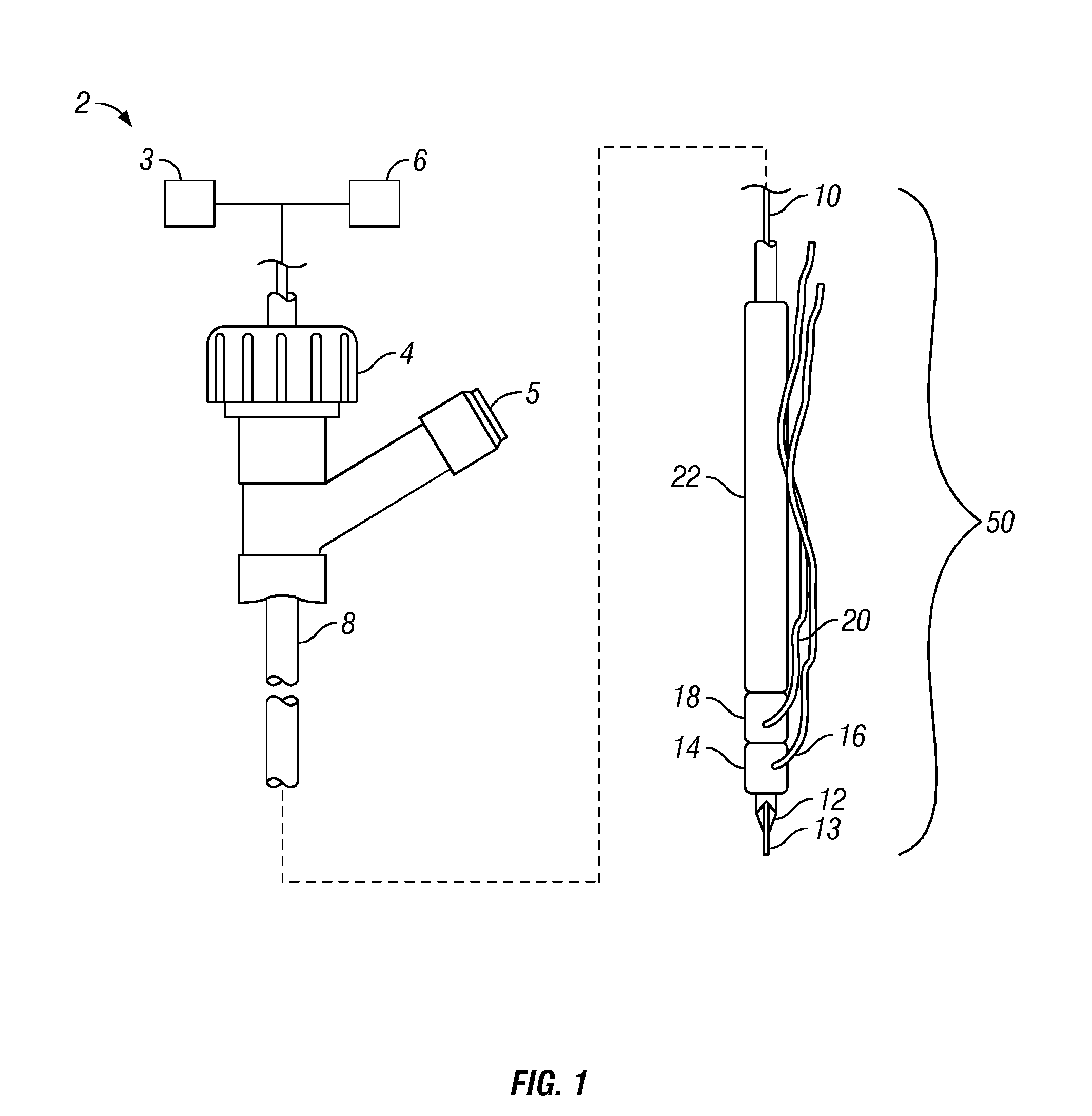
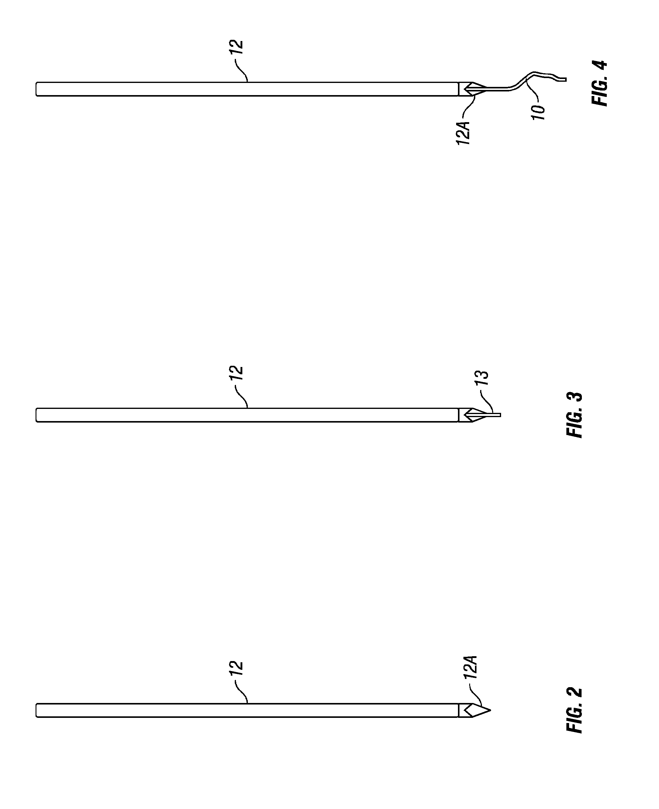
[0036]FIG. 1 is a schematic view of an exemplary embodiment of a needle-electrode anchor system. Without limitation, the needle-electrode anchor system can be particularly useful in gastrointestinal surfaces, such as abdominal walls, colon, esophageal tissues, and other tissue portions having walls that ...


PUM


Abstract

The disclosure provides a needle-electrode anchor system having a needle and an optional electrode with one or more anchors. The system can provide an electrical cutting current to the needle-electrode to create an opening in a tissue portion. An anchor coupled to the needle-electrode can be pushed through the opening with a pusher and pulled into position to set the anchor on a distal surface of the opening. If the tissue portion is to be approximated to another tissue portion, the system can be relocated to another tissue portion and another opening created with the cutting current with another anchor pushed through the opening and secured on a distal surface. Lines coupled to the anchors can be pulled together, approximating the tissue portions. If the tissue portion is to be retracted, an anchor line can be grasped to retract the tissue portion from an adjacent tissue portion.

Description

CROSS REFERENCE TO RELATED APPLICATIONS[0001]This application claims the benefit of U.S. Provisional Appl. No. 60 / 885,113, filed Jan. 16, 2007.STATEMENT REGARDING FEDERALLY SPONSORED RESEARCH OR DEVELOPMENT[0002]Not applicable.NAMES OF PARTIES TO A JOINT RESEARCH AGREEMENT[0003]Not applicable.REFERENCE TO APPENDIX[0004]Not applicable.BACKGROUND[0005]1. Field of the Invention[0006]The present disclosure medical procedures. More particularly, the disclosure relates to setting tissue anchors for tissue approximation and retraction in medical procedures.[0007]2. Description of Related Art[0008]During medical procedures on tissues surfaces, it is often desirable to pull tissue portions toward each other, generally known as “approximation”. For example, the tissue portions can be adjacent to a wound that needs suturing or other closure. The gap between adjacent sides of the wound may be so large as to make the closure tenuous and time consuming. Other medical procedures often benefit from...

Claims


Application Information

Patent Timeline
IPC IPC(8): A61B17/04
CPCA61B2018/00273A61B2017/0445A61B17/0401A61B2017/00876A61B17/0487A61B2017/0404A61B2019/462A61B2017/0464A61B17/0469A61B18/1477A61B2017/0409A61B2017/22038A61B2017/061A61B2090/062
Inventor RAJU, GOTTUMUKKALA S.
Owner BOARD OF RGT THE UNIV OF TEXAS SYST
Learn More